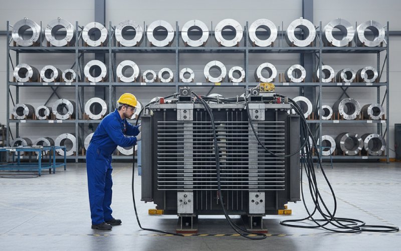
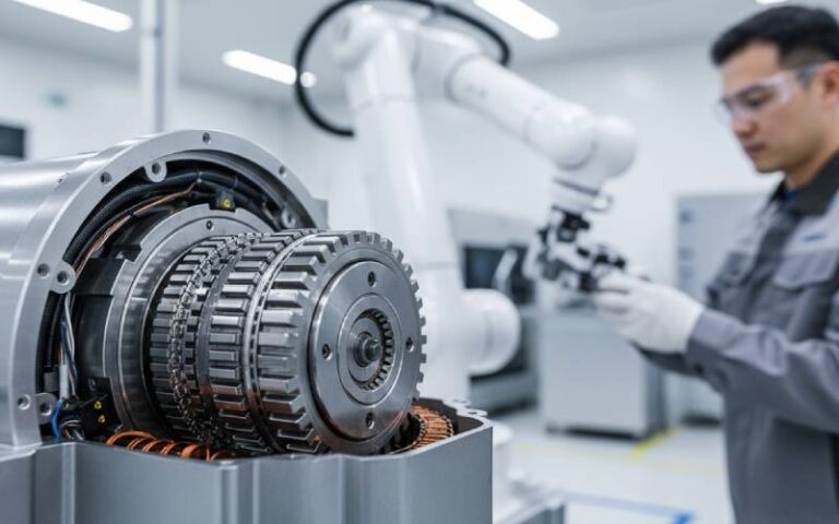
Deje que las pilas de laminación de Sino potencien su proyecto.
Para agilizar su proyecto, puede etiquetar las pilas de laminación con detalles como tolerancia, material, acabado superficial, si se requiere o no aislamiento oxidado, cantidady mucho más.
Laminado CRGO frente a núcleo nanocristalino: dónde gana cada uno
De qué trata este artículo: Pilas de laminación CRGO vs núcleos nanocristalinos, desde el punto de vista del diseño y las compras.
Índice
1. Contexto rápido: lo que ya sabe
Ya sabes lo básico:
CRGO = laminados de acero al silicio de grano orientado, alta densidad de flujo, excelente para transformadores de potencia de 50/60 Hz.
Nanocristalino = cinta a base de Fe, tamaño de grano nanométrico, permeabilidad muy alta, pérdidas muy bajas de baja a media-alta frecuencia.
Las hojas de datos dicen cosas similares, con fuentes ligeramente diferentes. La cuestión es cómo se comportan cuando se construyen núcleos y pilas de laminación reales, y en qué aspectos cada opción se gana realmente su sustento..
2. Números magnéticos uno al lado del otro (realistas, no perfectos)
Pongamos en una página los valores típicos de un catálogo. Son los siguientes cifras aproximadas de ingeniería, no los límites de diseño.
Parámetro (típico)
Pila de laminación CRGO
Núcleo bobinado de cinta nanocristalina
Densidad de flujo de saturación Bs
≈ 1.8-2.0 T
≈ 1.2-1.3 T
Permeabilidad relativa µr (intervalo utilizable)
≈ 30,000-50,000
≈ 80.000-150.000 (sintonizable hacia arriba, incluso más)
Pérdida en el núcleo @ 50 Hz, 1,7 T
≈ 0,9-1,6 W/kg (Hi-B en el extremo inferior)
No suele funcionar tan fuerte a 50 Hz
Pérdida en el núcleo @ 20 kHz, 0,1 T
>150 W/kg
<15 W/kg
Temperatura de Curie
≈ 730-750 °C
≈ 550-580 °C
Resistividad eléctrica
≈ 40-50 μΩ-cm
≈ 100-120 μΩ-cm
Factor típico de apilamiento / laminación
~0,96 para buenas pilas escalonadas
~0,75-0,80 para cintas enrolladas
Banda de frecuencia del punto dulce
50/60 Hz, hasta unos cientos de Hz
De unos pocos kHz a decenas de kHz (depende del flujo)
Geometría en la práctica
EI, núcleos escalonados, piernas enrolladas, reactores
Toroides, núcleos cortados, núcleos en C, pilas especiales
Coste relativo del material por kg
Baja
Más alto
Potencial de densidad de potencia relativa
Limitado por las pérdidas a f
Muy fuerte en la gama de frecuencias medias
Los datos anteriores combinan ejemplos publicados de los principales proveedores y notas de material, no sólo una hoja de marketing.
Un par de cosas saltan a la vista:
CRGO transporta más flujo antes de la saturación, lo que importa para corriente de defecto soportada y de irrupción.
El nanocristalino reduce las pérdidas de alta frecuencia en aproximadamente un orden de magnitud en la misma inducción.
Esos dos hechos ya dejan entrever dónde gana cada uno.
3. Donde las pilas de laminación CRGO siguen siendo la opción obvia
3.1. Hierro grande a 50/60 Hz
Si estás haciendo Transformadores de potencia o distribución MT/BT a frecuencia de red, es casi seguro que el núcleo principal está laminado con CRGO:
La eficiencia en el rango 98-99% es alcanzable con los modernos grados Hi-B (≤0,9 W/kg @ 1,7 T, 50 Hz, con trazado láser).
Un factor de apilamiento de alrededor de 0,96 en buenas construcciones de solapamiento por pasos significa que no estás desperdiciando área de ventana en aire.
Para una unidad de 1 MVA a 50 Hz, el cambio a nanocristalino para los tramos principales no suele ser una opción viable:
Tendrías que correr Bs inferior para controlar las pérdidas a 50 Hz, por lo que el volumen del núcleo sube.
La estructura mecánica se vuelve complicada: los bloques bobinados con cinta sometidos a grandes cargas de sujeción y transporte no están contentos a menos que se rediseñe todo a su alrededor.
Así que para transformadores de potencia clásicos, las pilas de laminación CRGO ganan por un amplio margen en coste por kVA, practicidad y ecosistema.
3.2. Alto flujo, servicio de cortocircuito, “modo de abuso”.”
Siempre que la especificación huela:
alta corriente de fallo
entrada larga
limitaciones térmicas en aceite o resina
...apreciarás tener ~1.9-2.0 T saturación en lugar de ~1,25 T.
Los nanocristalinos pueden hacer frente a una inducción elevada en casos especiales, pero la cuestión es sencilla: si el núcleo vive cerca del límite durante los fallos, CRGO suele ser más seguro.
3.3. Tamaños de bastidor muy grandes y fabricación local
En núcleos grandes:
Puede cortar, apilar y volver a apilar las láminas CRGO localmente, utilizando plantillas conocidas.
Los talleres saben cómo reconstruirlos.
Puede abastecerse de acero eléctrico en varias acerías, cortarlo localmente y mantener bajo control el riesgo de los proveedores.
Existen núcleos nanocristalinos de esos tamaños (nanopilas laminadas, no sólo toroides), pero son artículos especiales con menos proveedores y ventanas de proceso más ajustadas.
Si su equipo de compras desea segunda y tercera fuentes para cada pieza estratégica, las pilas CRGO simplifican la vida.
4. Donde brillan los núcleos nanocristalinos
Ahora viene lo interesante. Lugares donde la CRGO es técnicamente posible, pero no aconsejable.
4.1. Potencia de frecuencia media (de unos pocos kHz a decenas de kHz)
Piensa:
transformadores de estado sólido
Cargadores rápidos para vehículos eléctricos
inversores solares y de almacenamiento
convertidores de enlace de frecuencia media
En esa banda, Explota la pérdida de núcleo de CRGO. El nanocristalino mantiene la calma:
Datos típicos: a 20 kHz, 0,1 T, los núcleos nanocristalinos pueden situarse por debajo de 15 W/kg frente a >150 W/kg para el acero al silicio CRGO - una diferencia de aproximadamente 10×.
Una permeabilidad elevada (hasta ~80.000 y más) significa menos espiras, trayectos de cobre más cortos y transformadores compactos a esas frecuencias.
Así que si su frecuencia de conmutación fundamental o dominante está en la región de 5-50 kHz y la potencia no es diminuta, el nanocristalino suele ser el favorito, no la ferrita ni el CRGO.
4.2. Choques EMI y de modo común
Los choques de modo común y los filtros EMI son territorio clásico de los nanocristalinos:
µr muy alta en una banda ancha → gran inductancia en un toroide pequeño.
Baja pérdida incluso bajo ondulación HF → filtros más fríos a la misma atenuación.
Con CRGO tendrías:
quemar demasiada pérdida a alta frecuencia, o
necesitan dimensiones absurdas para alcanzar la misma impedancia.
Así que si su BoM tiene múltiples grandes choques CM de ferrita, el cambio a núcleos nanocristalinos bobinados en cinta suele ser la mejora de densidad más sencilla.
4.3. Transformadores de medida
Para transformadores de corriente (TC) y transformadores de precisión para instrumentos:
La alta permeabilidad y la baja coercitividad reducen la corriente magnetizante y mejoran la linealidad.
La mayor resistividad (~100-120 μΩ-cm frente a ~45 μΩ-cm del CRGO) ayuda a controlar las corrientes parásitas en los armónicos más altos.
Si el TC ve formas de onda distorsionadas -accionamientos, cargadores de VE, salidas de SAI-, los núcleos nanocristalinos tienden a mantener la precisión de relación y fase donde el acero al silicio empieza a divagar.
4.4. Sistemas ricos en armónicos de 50/60 Hz
A veces la fundamental sigue siendo 50/60 Hz, pero:
THD es feo
las cargas son electrónicas
la corrección del factor de potencia y los rectificadores arrojan componentes de alta frecuencia al núcleo
Toma, nanocristalino se comporta como “CRGO + ferrita de filtro en un solo material”. Usted consigue:
buen manejo del flujo con inducciones moderadas
fuerte atenuación de los componentes HF debido al perfil de permeabilidad y a la menor pérdida
Esa es una de las razones por las que se ven nanocristalinos en los modernos transformadores de tipo seco y reactores especiales destinados a la electrónica de potencia.
5. Bandas de frecuencias: ficha rápida de diseño
No son normas estrictas. Sólo una comprobación de cordura para la selección temprana:
0-200 Hz, gran potencia, MT/BT
Núcleo principal: Laminados CRGO casi siempre.
Nanocristalino sólo en pequeñas piezas auxiliares (CTs, sensores).
200 Hz-2 kHz
Si la inducción es baja y el tamaño es generoso: CRGO o amorfo aún pueden encajar.
Si usted está empujando la densidad o ver fuerte ondulación: nanocristalino se vuelve muy atractivo.
2-50 kHz
Transformadores de potencia: nanocristalino frente a ferrita; el CRGO suele abandonarse pronto.
EMI: nanocristalino para reactancias compactas de alta corriente; ferrita para puntos más baratos y fríos.
>50 kHz
La ferrita sigue dominando, con algunos núcleos nanocristalinos y de polvo avanzados para diseños nicho de alta potencia.
Si su diseño se sitúa exactamente en un límite, espere iteraciones, no una única respuesta “correcta”.
6. Coste, disponibilidad y riesgo - desde la silla del comprador
6.1. Material + coste de transformación
Laminados CRGO
Bajo coste por kg, alto factor de apilamiento, residuos razonablemente bajos con un buen anidado.
El corte, el punzonado escalonado y el apilado son procesos maduros en todo el mundo.
Núcleos nanocristalinos
Mayor coste por kg, menor factor de apilamiento, más fases de proceso (bobinado, recocido, revestimiento, encapsulado o encamisado).
Pero a menudo utilizas menos volumen central debido a la mayor µr y a que su frecuencia es más alta.
A nivel de pieza, el nanocristalino puede parecer caro. A nivel nivel del sistema, una vez que el factor:
cobre reducido
imanes más pequeños
hardware térmico más pequeño
...puede aterrizar más barato por kW manejado, sobre todo en convertidores de frecuencia media.
6.2. Plazo de entrega y estrategia de segunda fuente
Tiras y laminados CRGO:
Muchos molinos, muchas cortadoras.
Alternativas más fáciles de calificar, aunque las calificaciones difieren.
Nanocristalino:
Menos productores de aleaciones y fábricas de núcleos.
Las recetas de recocido y los procesos de revestimiento varían de un proveedor a otro.
Si su proyecto es crítico para la seguridad o de larga duración, merece la pena diseñar sobres mecánicos y ventanas apilables de laminación que puede aceptar al menos dos geometrías de núcleo nanocristalino, no sólo una pieza patentada.
7. Trampas mecánicas y de fabricación que deben evitarse
No están en la hoja de datos, pero rinden.
7.1. Sujeción excesiva de núcleos nanocristalinos
La cinta nanocristalina es:
fino
agudo
algo quebradizo
Un exceso de apriete o una presión desigual pueden:
aumentar la pérdida
crear puntos calientes
incluso agrietar el revestimiento del núcleo
Diseñe su esquema de sujeción para tratar el núcleo de la herida como un componente de precisión, no como una pila de laminados pesados.
7.2. Tratar el CRGO como si tuviera un factor de apilamiento infinito
Para pilas de laminación:
Las rebabas, una limpieza deficiente y una alineación descuidada pueden acabar silenciosamente con el supuesto factor de apilamiento de 0,96 y con la eficiencia.
Los pequeños espacios de aire entre paquetes se manifiestan como mayores pérdidas en vacío y ruido.
Así que si estás persiguiendo una eficiencia fraccionaria, el control del proceso de fabricación es tan importante como la calidad del material.
7.3. Ignorar el contenido de frecuencia de la forma de onda
Los diseños a veces dicen “transformador de 50 Hz” cuando la carga es un armario de transmisión:
Choppers de bus CC
ondulación de conmutación
alto contenido en armónicos
En ese caso:
El uso de pilas CRGO puras dimensionadas para 50 Hz RMS puede dar lugar a un calentamiento desagradable del núcleo bajo formas de onda reales.
A enfoque compuesto (patas principales CRGO + núcleos auxiliares o filtros nanocristalinos) suele alcanzar un mejor equilibrio.
8. Vía de decisión práctica: Laminado CRGO frente a núcleo nanocristalino
Puedes comprobar la cordura de tu elección de material con unas cuantas preguntas contundentes.
La frecuencia de funcionamiento principal, ¿es ≤ 400 Hz y la potencia superior, digamos, a decenas de kVA?
Sí → Comenzar con Pilas de laminación CRGO.
No → Considere primero nanocristalino o ferrita.
¿Necesita soportar elevadas corrientes de entrada o de cortocircuito a alto flujo?
Sí → CRGO tiene más margen en Bs.
No → Los Bs más bajos del nanocristalino pueden estar bien; diseña en torno a ellos.
¿El núcleo también hace de filtro EMI / modo común o vive en una forma de onda muy distorsionada?
Sí → Los núcleos nanocristalinos para reactancias y transformadores auxiliares suelen ser mejores.
¿Su principal limitación es el volumen y el peso, no el coste de la materia prima?
Sí → El nanocristalino gana valor rápidamente, ya que la densidad de potencia importa más que el precio en kg.
¿Tiene capacidad de laminación local pero acceso limitado a núcleos especiales?
Sí → Las láminas CRGO pueden ser más seguras para el calendario hasta que madure la cadena de suministro.
Por supuesto, se pueden mezclar ambas cosas: La pila de laminado principal CRGO + TC nanocristalinos y choques CM en el mismo producto ya es habitual en los conmutadores y convertidores de potencia modernos.
9. Preguntas frecuentes: Laminado CRGO frente a núcleo nanocristalino
Q1. ¿Puedo colocar núcleos nanocristalinos en un diseño de transformador CRGO existente y esperar una mejora de la eficiencia?
Normalmente no. Nanocristalino quiere una densidad de flujo, diferentes utilización de ventanas, y a menudo diferentes refrigeración estrategia. Los intercambios directos uno a uno tienden a saturar el núcleo o a infrautilizar el material. Si desea beneficios nanocristalinos, trátelo como un nuevo diseño magnético, no como un grado de laminación de sustitución.
Q2. ¿Existen “pilas de laminación nanocristalina” como las pilas CRGO?
Sí, pero no son piezas básicas. Los investigadores y algunos fabricantes construyen núcleos laminados nanocristalinos apilando cintas tratadas o tejas cortadas con cinta, principalmente para electrónica de potencia de alta frecuencia donde no caben los toroides estándar. Por ahora, sin embargo, la mayoría de las piezas nanocristalinas comerciales que verá son: toroides (macizos o cortados) Núcleos C formas especiales de heridas Si su negocio son los transformadores de potencia clásicos, seguirá viviendo sobre todo en pilas de laminación CRGO durante un tiempo.
Q3. ¿Cómo se comparan los núcleos nanocristalinos con el metal amorfo?
A un alto nivel: Ambos tienen pérdida mucho menor que el CRGO a la frecuencia de línea. En muchos casos, el amorfo puede reducir las pérdidas en el núcleo hasta ~70% frente al acero al silicio convencional. Los nanocristalinos suelen mejorar a los amorfos en frecuencias más altas, con mayor permeabilidad y menor pérdida en la banda de decenas de kHz. Así que..: Para transformadores de distribución ultraeficientes de 50/60 Hz en grandes volúmenes: compiten los amorfos y los GOES avanzados. Para magnetismo de media frecuencia y EMI: el nanocristalino tiende a ganar.
Q4. ¿Es el nanocristalino excesivo para las SMPS de baja potencia?
A veces sí. Para un flyback de 20-50 W a 100 kHz: La ferrita es barata, fácil y suficientemente buena. El nanocristalino empieza a tener más sentido a medida que aumentan la potencia, la corriente o la polarización de CC, o cuando el tamaño está muy limitado. Para SMPS de mayor potencia (clase kW) con exigentes objetivos de EMI y eficiencia, transformadores y choques nanocristalinos puede ser una fuerte palanca.
Q5. ¿Qué debo decir a los compradores cuando me preguntan “por qué es tan caro este núcleo”?”
Tres puntos cortos suelen ayudar: A nivel de convertidor, pérdida y refrigeración cuestan más que el acero. La menor pérdida de núcleo puede reducir las necesidades de disipadores, ventiladores o refrigeración líquida. Una mayor permeabilidad significa menos cobre, menos vueltas y, a veces, PCB y montaje más baratos. En muchos proyectos, el volumen y el peso de los imanes son ahora limitaciones a nivel de sistema (espacio en el bastidor, embalaje del vehículo), no sólo elementos de línea en la lista de materiales. Si sigue sin funcionar, ejecute un simple coste por vatio ahorrado comparación entre los diseños CRGO y nanocristalinos. Las cifras tienden a hablar en voz baja pero clara.
Conclusión
Las pilas de laminación CRGO no van a desaparecer. Son imbatibles para grandes transformadores de baja frecuencia y para todo lo que funcione con alto flujo en condiciones de fallo.
Los núcleos nanocristalinos tampoco son mágicos. Solo inclinan las compensaciones a tu favor una vez:
aumenta la frecuencia
el contenido armónico se pone feo
o persigue un magnetismo compacto y eficiente en la electrónica de potencia.
Si trata a ambos como herramientas, no como equipos, y los alinea con la banda de frecuencia y el deber adecuados, su pilas de laminación, núcleos bobinados y decisiones de compra todo empezará a alinearse mucho más fácilmente.
Cheney es un ingeniero de aplicaciones sénior de Sino con una gran pasión por la fabricación de precisión. Es Ingeniero Mecánico y posee una amplia experiencia práctica en fabricación. En Sino, Cheney se centra en optimizar los procesos de fabricación de pilas de laminación y en aplicar técnicas innovadoras para conseguir productos de pilas de laminación de alta calidad.
Folleto de nuevos productos
Introduzca su dirección de correo electrónico y le enviaremos el folleto más reciente.
Deje que las pilas de laminación de Sino potencien su proyecto.
Para agilizar su proyecto, puede etiquetar las pilas de laminación con detalles como tolerancia, material, acabado superficial, si se requiere o no aislamiento oxidado, cantidady mucho más.