¡Deje que los paquetes de laminaciones de Sino impulsen su proyecto!
Para acelerar su proyecto, puede etiquetar los paquetes de laminaciones con detalles como tolerancia, material, acabado superficial, si se requiere o no aislamiento oxidado, cantidad, y más.
Root-Cause Analysis for Rising No-Load Current: A Diagnostic Checklist
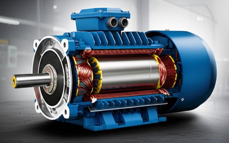
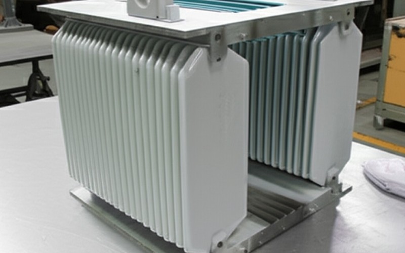
En corriente en vacío rises above expected levels in rotating or stationary electrical equipment—induction motors, power transformers, both common in lamination-stack assemblies—the underlying cause can range from a measurement artifact to critical core damage. The diagnostic path is the same in principle, but the proof methods diverge at a handful of physical forks: where the magnetic circuit sits, whether the iron is built up from laminations or a solid core, and whether saturation, eddy-current, or inter-laminar insulation is the dominant loss mechanism. This checklist is organized by verification cost, cheapest first.
Índice
What Rising No-Load Current Tells You—and What It Does Not
An elevated no-load current reading is a condition indicator, not a diagnosis. It signals that the magnetic circuit requires more ampere-turns than design intent, that core or winding losses have increased, or—most often—that test conditions differ from the baseline reference.
Priority triage:
Measure first, conclude later. A significant proportion of “rising current” cases trace to meter placement, ambient voltage deviation, or incomplete mechanical decoupling. Verify your test setup before diagnosing the equipment.
Context determines urgency. Stable elevated current with no thermal, acoustic, or vibration symptoms may warrant monitoring rather than immediate shutdown. Sudden rises accompanied by heat, noise, dissolved gas (transformers), or insulation degradation require prompt removal from service.
Do not cycle power hoping the issue self-resolves. Repeated energization under fault conditions accelerates damage.
Normal No-Load Current: Defining the Baseline
For Induction Motors
No-load current (also termed magnetizing current or corriente de excitación when the rotor is mechanically decoupled) is the current drawn when the motor shaft is free of mechanical load. The current serves three functions:
Magnetizing component (Im): Establishes the rotating magnetic field; typically 70–90% of total no-load current in standard 4-pole designs. This component is largely reactive (lagging power factor ~0.2–0.3 at no load vs. 0.8–0.9 at rated load).
Core-loss component (Ic): Supplies hysteresis and eddy-current losses in stator and rotor laminations.
Friction and windage: Mechanical losses; usually minor relative to magnetic components.
For Power Transformers
Excitation current is drawn by the primary winding when secondary windings are open-circuited. It magnetizes the core and supplies no-load losses. The reactive component dominates; the real (watts) component corresponds to core loss and can be measured separately with a wattmeter.
Typical Percentage of Full-Load Current
Critical context: Published guidelines reflect different design eras, nameplate standards (NEMA vs. IEC), and machine size classes. Always prioritize comparison against OEM factory test data or your own commissioning baseline rather than generic percentages.
Higher percentage due to lower magnetizing reactance per unit
Large motors (>100 hp / >75 kW)
20–30%
Improved magnetic design efficiency
NEMA 4-pole average
33–40%
Consistent with EASA technical guidance on no-load current expectations
Submersible / special-duty motors
40–60%
Longer magnetic path; design trade-offs
Decision rule when OEM data is unavailable:
Use machine size class as first filter (see ranges above).
Within size class, use recuento de polos as second filter: higher pole counts shift the range upward because magnetizing reactance scales with synchronous speed.
Utilice enclosure / cooling as third filter: TEFC (totally enclosed fan-cooled) and submersible designs often run 5–10 percentage points above the same-rated ODP (open drip-proof) unit.
Compare against identical design (same frame, same manufacturer revision) before accepting generic percentages as the baseline.
When in doubt, request factory test sheets. Major manufacturers provide no-load current and watts under standardized IEEE 112 (motors) or IEEE C57.12.90 (transformers) procedures.
Transformers: Excitation current is typically 0.5–3% of rated current for power transformers, higher for distribution units and smaller ratings.
Action threshold (motors): Current consistently above 45% of nameplate FLA at rated voltage and temperature, with no change in operating conditions, warrants investigation. For transformers, compare against factory no-load test reports at the same tap position and test voltage.
Measurement & Test Conditions: Rule Out False Positives First
Before attributing elevated current to equipment degradation, confirm test conditions match the reference baseline. Incorrect measurement accounts for a disproportionate share of field “faults.”
Mechanical Decoupling
Motors: Verify the driven load is fully disconnected. Belt drives, gear reducers, couplings, pump seals, or brake assemblies that remain engaged will elevate current. Hand-rotate the shaft (power isolated, LOTO applied) to confirm free movement. Compare readings with coupling connected vs. disconnected.
Transformers: All secondary windings must be open-circuit. Residual connected instrumentation or grounding practices per manufacturer specifications may influence readings but should be documented and consistent across tests.
Voltage at Terminals
Measure, do not assume. Always record all three line-to-line voltages with a calibrated instrument. Variations from nameplate rating directly affect magnetizing current:
Below saturation: Magnetizing current scales approximately linearly with voltage (Im ∝ V / Xm, where Xm is magnetizing reactance).
Approaching or entering saturation: Current rises faster than voltage (Im ∝ V^n, where n > 1). A 10% overvoltage may yield 15–25% current increase in a saturated magnetic circuit.
Correction for comparison: If baseline data was recorded at rated voltage and the present test is at a different voltage (but both within linear region), apply:
I_corrected = I_measured × (V_rated / V_measured)
Precaución: This correction assumes linearity. If either voltage places the machine near saturation, correction factors become unreliable. Transformers operating under reduced-voltage field tests cannot be directly compared to factory full-voltage reports due to magnetizing impedance nonlinearity.
Voltage unbalance (phase-to-phase deviation) produces negative-sequence currents that induce counter-rotating flux, increasing effective magnetizing demand and rotor heating. Calculate unbalance as:
% Unbalance = (Max deviation from average / Average voltage) × 100
Current unbalance typically magnifies voltage unbalance by a factor of 6–10. NEMA MG-1, Part 14, limits acceptable voltage unbalance at the machine terminals to 1% and requires derating above that value (roughly 5% derate at ~3% unbalance, 25% derate at ~5%). During no-load testing, any current unbalance well above what the measured voltage unbalance predicts is a signal to check the supply cabling and terminals first, then the machine’s internal symmetry.
Frecuencia
Magnetizing current is inversely proportional to frequency (Im ∝ V/f). Under-frequency operation (common during generator startups, weak grid connections, or VFD commissioning errors) elevates excitation current and risks saturation. Confirm frequency is within ±1% of nameplate rating.
Thermal Stability
Winding and core temperatures affect resistance and, to a lesser degree, reactance. Allow the machine to thermally stabilize before recording final readings—typically 15–30 minutes of continuous no-load operation for motors under 50 hp, longer for larger units and transformers. Compare readings taken at similar ambient temperatures or apply temperature correction per IEEE 43 (motors) and manufacturer guidelines (transformers).
Instrumentation & Meter Placement
True RMS meters required for VFD-supplied equipment or any waveform with harmonic content. Average-responding meters may under-read by 20–30% on PWM waveforms.
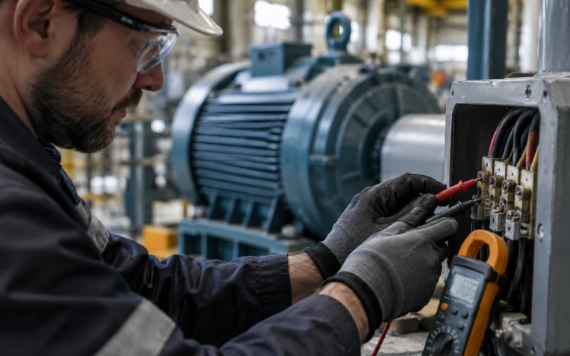
Clamp-on meters: Position the clamp well away from busbars, contactors, or other conductors to avoid stray magnetic field interference. When possible, take readings at the motor or transformer terminals rather than at the starter or switchgear.
Verify instrument accuracy: Test the meter on a known load or against a second calibrated instrument before concluding equipment is faulty. Record kW, kVAR, power factor, and harmonic distortion (THD) alongside current—current alone does not distinguish magnetizing issues from other anomalies.
Replicate the reading without altering setup to establish measurement repeatability before comparing to baseline.
Documentation Requirements
Comparison is meaningless without consistent reference points. Each no-load test record should capture:
Date, time, ambient temperature
All three phase currents, all three line voltages, frequency
Power (kW), reactive power (kVAR), power factor
Winding temperature (motor) or oil temperature (transformer)
Tap position (transformers), connection configuration (motors: wye vs. delta)
Instrument make/model/calibration date
Asset ID or serial number
For transformers: Note whether excitation test was conducted per IEC 60076-1 or IEEE C57.12.90 procedures, test voltage magnitude, and whether temperature corrections were applied (note: excitation current tests typically do no apply temperature correction, unlike resistance tests).
Supply-Side Causes: Start Where Verification Is Cheapest
Overvoltage
Most common cause of elevated no-load current in motors with stable baselines. Voltage 5–10% above nameplate shifts the B-H curve toward saturation, producing disproportionate current increases. Remedies:
Verify utility supply is within NEMA ±10% tolerance (though even in-tolerance overvoltage elevates current).
Coordinate with utility or facility electrical team to adjust transformer tap settings if chronic overvoltage is present.
Derate the motor per NEMA MG-1 Part 14 if operation above rated voltage is unavoidable (derating factor ~0.95 for +10% voltage).
Voltage or Current Unbalance Beyond Measurement Error
Phase-to-phase voltage differences generate negative-sequence flux. Even small voltage unbalances (~3%) can produce current unbalances exceeding 20%. Causes:
Unbalanced single-phase loads on three-phase system
Loose or corroded connections at terminals, fuse holders, or contactors
Open or degraded phase in supply cabling
Internal winding asymmetry (requires correlation with other tests; see Winding Resistance section)
Diagnostic: Swap motor leads (with power isolated) to determine whether unbalance follows the supply conductors or remains with specific motor phases. If unbalance follows the supply, address upstream issues before attributing fault to the motor.
Harmonic Distortion / Non-Sinusoidal Supply
VFD-supplied motors and transformers feeding rectifier loads exhibit elevated excitation current due to harmonic content. Additional heating from harmonic copper and core losses may not correlate directly with fundamental-frequency current but degrades insulation over time. Mitigation:
Install dV/dt filters or sine-wave filters at VFD output
Use reactors (3–5% impedance) to limit harmonic injection
For VFD-coupled motors, confirm that drive is configured for correct motor parameters (rated voltage, current, frequency, and load inertia)
Single-Phasing (Loss of One Phase)
Remaining two phases will carry approximately 1.73× rated current under loaded conditions; even at no load, unbalanced magnetization and induced currents in the remaining phases will produce elevated and highly asymmetric current readings. Single-phasing will rapidly overheat windings. Remove from service immediately if detected.
Magnetic Circuit & Winding Causes: Requires Shutdown & Testing
When supply and measurement conditions are verified clean, elevated no-load current points to changes in the magnetic circuit, winding configuration, or core condition.
Air Gap (Motors)
Air gap between rotor and stator is the dominant reluctance in the magnetic circuit. Excessive or uneven air gap increases magnetizing demand:
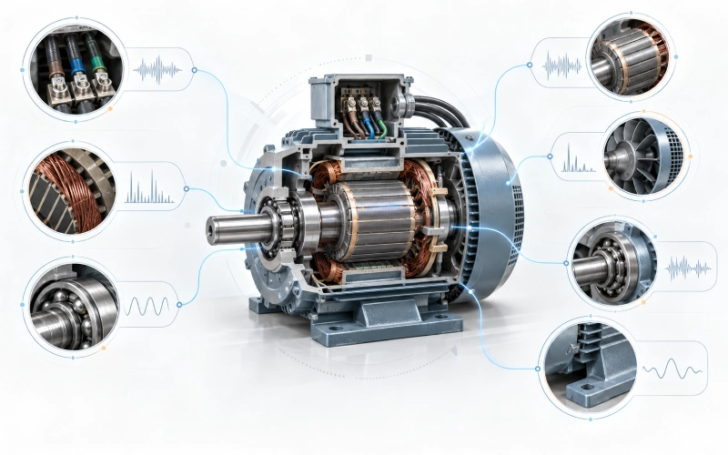
Rotor eccentricity (static or dynamic): Unequal air gap around rotor circumference. Typically accompanied by once-per-revolution or twice-per-revolution vibration and audible hum at line frequency.
Bearing wear, bent shaft, or frame distortion leading to misalignment.
Rotor diameter reduction: If rotor has been machined (skimmed) during repair, air gap increases permanently.
Diagnosis: Measure air gap at multiple points around the circumference with feeler gauges (motor de-energized, rotor rotated to access all positions). Compare to OEM specifications. Typical air gaps range from 0.015″ to 0.060″ depending on frame size; deviations >10% from design are significant.
Turn-to-turn shorts bypass part of the intended turns, increasing the current in remaining turns and altering flux distribution. Symptom: elevated and asymmetric no-load current, usually accompanied by localized heating (thermography) or insulation odor.
Tests (motors):
Megohmmeter (insulation resistance test): Phase-to-phase and phase-to-ground readings per IEEE 43. Recommended minimum one-minute insulation resistance at 40 °C: for form-wound windings made before ~1970, R_min = kV + 1 MΩ (where kV is the machine rated voltage); for most form-wound windings made after ~1970, 100 MΩ; for random-wound stators rated below 1 kV, 5 MΩ. Correct for temperature using the standard approximation (insulation resistance roughly doubles for every 10 °C decrease in temperature); compare readings at a common reference (typically 40 °C), not at room temperature.
High potential (hipot) test: Per IEEE 95, applied voltage 2× rated + 1000 V AC for 1 minute (AC) or higher for DC test. Destructive—do not repeat unless essential.
Surge comparison test: Compares the voltage withstand pattern of each phase using identical surge waveforms. Reveals turn insulation breakdown not detected by standard low-voltage tests.
Rotor open-circuited, stator energized, rotor spin direction check: With stator energized at rated voltage (with current limiting), hand-spin rotor in normal and reverse direction. Asymmetric current consumption indicates internal winding faults.
Megohmmeter + Doble or equivalent power-factor testing: For high-voltage equipment, power-factor tip-up tests identify ionization in insulation voids that would not appear on routine insulation resistance.
For transformers: Perform turns-ratio test (per IEC 60076-1 or IEEE C57.12.90), excitation current tests (inter-winding and per-tap), and sweep frequency response analysis (SFRA) to detect winding movement or distortion.
Stator/Rotor Bar or End-Winding Failures
Cast aluminum rotor squirrel-cage bars or bars damaged by overheating or contamination cause current asymmetry. Rotor faults typically:
Affect all three line currents equally when measured at the motor terminals (unlike supply or stator asymmetry)
Are sensitive to rotor position—reading varies slightly with manual rotation
Increase the negative-sequence component relative to the positive sequence
Core / Lamination Damage
Core damage is among the most serious root causes because remediation is expensive or impossible.
Mechanisms:
Interlaminar insulation breakdown: Once effective, the thin insulation (coating, oxide layer, or varnish) between lamination layers limits eddy-current paths. If compromised—through thermal aging, mechanical scoring during a rotor event, or contamination—eddy currents increase dramatically, raising both no-load current and core losses.
Lamination shorts at end plates, through-bolts, or keyway edges: Conductive bridges bypass individual laminations.
Core winding saturation: Can occur when severe inter-laminar shorting draws sufficient local current to heat and saturate adjacent material.
End-region heating from stray flux: Particularly relevant for large motors and transformers.
Diagnosis:
Inspección visual of accessible core surfaces for discoloration (blue/black indicates localized overheating >200°C).
Ring flux test / loop test: Energize a temporary winding with 5–10% rated voltage; search for localized hot spots with thermal imaging or thermal sensors at lamination edges.
EL-CID (Electromagnetic Core Imperfection Detection): Low-voltage test for inter-laminar insulation faults in stator cores. Per IEC 60034-15, used after rewinds or suspected core damage.
Watts-loss comparison between rated and reduced-voltage tests (typically 50–110% of rated voltage), to identify non-linear core loss increases.
Prueba de pérdida de núcleo at rated flux and frequency to quantify loss component directly—compare with factory test or frame-benchmarked repair-shop data.
Inter-Laminar Resistance and Stacking
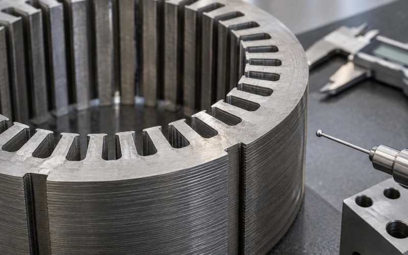
Interlaminar insulation quality and stacking methods determine inter-laminar resistance, which directly affects eddy-current losses and therefore no-load current.
Effect of interlaminar resistance on core loss: Eddy-current losses in a stacked core are inversely related to inter-laminar resistance. In the linear region of the material’s B–H curve, doubling effective inter-laminar resistance can approximately halve the eddy-current component of core loss. Manufacturing specifications set a minimum surface insulation resistivity for each lamination as measured per ASTM A717/A717M (Franklin tester), and set a minimum inter-laminar resistance for the assembled stack. The specific numerical targets vary by coating class (per ASTM A976 for classification of electrical steel surface insulations) and by the equipment OEM; do not treat any single published figure as universal.
Stacking factor effects: Higher stacking factor (more steel per unit volume) reduces required excitation but also requires precise insulation between layers. Typical targets are 95–98%; below this threshold, magnetic performance degrades.
Manufacturing process contributors: The way laminations are handled, cleaned, coated, stacked, and clamped affects interlaminar resistance. Contamination from oil, moisture, or particulate can create conduction paths.
Diagnosis for inter-laminar resistance:
Surface insulation resistivity measurement on individual laminations per ASTM A717/A717M (Franklin test method) and inter-laminar resistance measurement on assembled stacks per ASTM A937/A937M.
Visual assessment for edge burrs or coating damage.
Trend monitoring on assembled cores before final varnish or encapsulation steps.
Repair, Rebuild, or Replace: The Core Damage Decision Matrix
When core damage is confirmed, the question is not “can it be fixed” but “what level of remediation is economically and operationally justified?”
Condition
Acción
Rationale
Localized inter-laminar shorts at accessible locations (end plates, keyways, through-bolts)
Repairable in situ. Open the affected area; clean, re-insulate individual laminations, re-test.
Limited scope; full rewind or restack not required.
Widespread inter-laminar shorts detected by EL-CID or ring test
Repairable but costly. Requires core disassembly and possibly restacking. Cost may approach new core cost for small/standard units.
Effective but labor-intensive; assess against replacement cost.
Melted or mechanically damaged core sections from rotor-stator rub, severe fault events
Generally not repairable in situ. Section replacement or full core replacement typically required.
Heat-affected zones alter magnetic properties permanently; localized repair leaves residual losses.
Stacked core with multiple shorted zones after a major thermal event (e.g., winding failure that cooked the core)
Investigate before returning to service. Re-strike and wedging operations may have damaged inter-laminar insulation or changed stacking pressure.
Field reports document this pattern; verify before final commissioning.
Repair tolerance benchmarks:
Core loss increase after repair: Should not exceed 10–15% above factory baseline for a successful repair. Increases of 20–40% indicate marginal repairs that may pass short-term testing but reduce efficiency and accelerate aging.
Inter-laminar resistance after repair: Target values matching original specification. If measured resistance drops significantly post-repair, insulation was likely damaged during disassembly.
Persistent elevated no-load current after verified clean supply, balanced voltages, and good insulation tests is the most common presentation of core damage. Insist on core-loss testing and visual end-region inspection before approving a motor or transformer for continued service under such conditions.
Capacity rerate option: If core damage is contained and confirmed non-progressive (e.g., from a one-time event with stable readings over time), reducing operating flux density—either by derating voltage or by accepting a lower kVA rating—can restore acceptable excitation current at the cost of reduced output. This is an engineering compromise, not a fix; document the rationale and revised duty cycle.
Mechanical & Rotating-Equipment Causes
Although the primary diagnostic interest in this checklist is the magnetic circuit, mechanical conditions can elevate no-load current by increasing effective load on the shaft (motors) or introducing unwanted losses (transformers).
Misalignment, Coupling Engagement, or Brake Holding
These may not be “no-load” failures in the strict sense, but they mimic them when the test setup inadvertently retains partial mechanical load. Diagnose first by:
Manually rotating shaft (power locked out) and checking for sticking or hard spots
Verifying brake assemblies are fully released
Confirming driven equipment is truly disconnected
Worn Bearings or Sleeve-Bearing Issues (Motors)
Bearing failure increases friction torque and may force the rotor off-center (creating air-gap asymmetry). Check:
Bearing temperature after brief no-load run
Listen for abnormal noise (rolling-element bearings: grinding; sleeve bearings: rumble)
Inspect for oil leaks, discoloration, or contamination
Bent Shaft or Frame Distortion
Following impact, overspeed events, or severe short-circuit events, mechanical deformation may remain. Detect by:
Dial indicator rotation check on shaft journals and coupling face
Air gap measurement at multiple rotor positions (eccentricity >10% suggests deformation)
Cooling-Fan or Ventilation Obstruction
Blocked airflow raises winding and core temperature, increasing losses modestly and reducing magnetizing reactance. Clean ventilation paths and confirm fan rotation direction (reversing a TEFC or TEAO fan can halve cooling effectiveness).
Complementary Tests That Pin Down the Diagnosis
Once measurement and supply conditions are ruled out, the following tests distinguish between the remaining causes with increasing levels of invasiveness and cost.
Insulation Resistance (IR) and Polarization Index (PI)
What it tells you: Moisture, contamination, insulation aging—not directly no-load current, but a necessary baseline before any further energized testing.
Procedure (per IEEE 43):
Megohmmeter at 500 V DC (low-voltage motors) up to 5000 V DC (high-voltage equipment)
Record reading at 60 seconds and 10 minutes
PI = R(10min) / R(1min). Values >2 indicate dry, sound insulation; <1 indicates moisture or contamination
Winding Resistance
What it tells you: Turn-to-turn shorts (low resistance), loose connections (high or unstable resistance), and balance between phases.
Procedimiento:
Use a low-resistance ohmmeter or Kelvin bridge
Measure phase-to-phase or terminal-to-terminal resistance with motor de-energized
Compare across phases. Imbalance >3% warrants investigation
For transformers: measure HV and LV windings; compare to factory values at the same temperature
Pitfall: Resistance readings can appear normal even with significant turn insulation breakdown. Surge comparison tests are required for definitive turn-to-turn assessment.
Surge Comparison Test
What it tells you: Turn-to-turn and turn-to-ground insulation integrity—the test most directly correlated with no-load current anomalies caused by winding faults.
What it tells you: Inter-laminar insulation faults in stator cores, especially useful post-rewind or after suspected core damage.
Procedimiento: Per IEC 60034-15. Low-voltage test that detects circulating currents between laminations; faults register as elevated signals on a Chattock potentiometer coil placed in the core.
Vibration & Acoustic Analysis (Motors)
What it tells you: Mechanical conditions (air-gap eccentricity, bearing wear, loose core) that may elevate no-load current.
Procedimiento: Vibration spectrum at de-energized (for looseness) and energized no-load conditions. Acoustic monitoring with ultrasonic or audio-frequency analyzers detects core hum at 100/120 Hz (line frequency harmonics)—changes in amplitude or tone correlate with magnetic circuit changes.
What it tells you: Insulation voids, delamination, and surface tracking that will degrade over time.
Procedimiento: Per IEC 60270, IEEE 1434, or ASTM D1868. Detects partial discharge inception voltage (PDIV) and discharge magnitude. Most relevant for equipment rated >4 kV.
Transformer-Specific Considerations: Where the Physics Diverges
For power and distribution transformers, the same checklist applies, but several tests and tolerances differ due to the transformer’s stationary magnetic design.
Excitation Current Test (Per IEEE C57.12.90 or IEC 60076-1)
Energize the transformer at rated voltage and frequency from one winding with all others open-circuited
Measure current and power; compare to factory data and between phases (three-phase units)
Acceptable deviation: ±10% from factory reading; deviation >25% suggests inter-winding faults, shorted turns, or core damage
Tap position matters: Always test at the same tap; tests at different taps are not directly comparable
Turns Ratio Test (TTR)
Verifies correct turns ratio between windings at each tap position
Deviations indicate shorted turns or winding damage
Perform before and after any major disturbance
Sweep Frequency Response Analysis (SFRA)
Detects winding deformation, displacement, or core movement
Used after through-fault events, transportation, or seismic events
Baseline comparison is essential; first-time SFRA serves as the reference for the equipment’s life
Dissolved Gas Analysis (DGA)
Tracks insulation breakdown products in oil-immersed transformers
For elevated excitation current specifically: Watch for acetylene (C₂H₂) and hydrogen (H₂) which indicate arcing; methane (CH₄) and ethylene (C₂H₄) which indicate thermal faults
Cautions: DGA alone does not pinpoint excitation current causes; correlation with electrical tests and history is required
Bushing and Tap Changer Integrity
Capacitance and dissipation factor (tan δ) testing of bushings
Tap changer contact resistance and continuity
Degraded bushings can increase apparent excitation current through partial discharge and altered capacitance
Operational Guidance: When to Run, When to Derate, When to Remove
Stable Elevated Current Without Other Symptoms
Recommendation: Continued operation with monitoring.
Increase surveillance frequency (thermal imaging weekly; periodic insulation tests quarterly)
Compare against manufacturer guidelines for acceptable variation
Recognize that elevated current is not synonymous with imminent failure. Machines have been documented to run for extended periods with no-load current well above the expected percentage, provided winding temperature, bearing temperature, acoustic signature, and vibration stay within their own baselines. The rule is: current alone is a symptom, not a verdict—cross-check against thermal and mechanical evidence before condemning a machine.
Structural caveat: “Stable” must be demonstrated, not assumed. Trend data over multiple measurement cycles (weeks to months) is required to characterize stability. A single elevated reading is not a trend; a documented trajectory is.
Elevated Current With Progressive Symptoms
Recommendation: Planned removal.
Rising temperature trends
Increasing vibration or noise amplitude
Accelerating insulation test degradation (declining PI, rising DF)
For transformers: increasing DGA gas concentrations or rates
[ ] If all electrical tests pass: investigate mechanical causes (air gap, bearings, alignment, cooling)
[ ] Document final diagnosis, supporting data, and recommended action
Resumen
Rising no-load current is most often a measurement or supply-side condition, less often a winding fault, and least often—but most seriously—a core/lamination condition. The diagnostic sequence above prioritizes cheap verification before invasive testing, supply-side causes before equipment-internal causes, and external symptoms before internal damage assessment.
Key actions for reliable diagnosis:
Always compare against your own baseline data when available; factory test data is the second-best reference; generic percentages are the weakest reference.
No single test tells the complete story. Layer multiple measurements over time.
Core damage is expensive to remediate. Confirm before approving replacement or major repair.
Document the investigation. The next engineer to see this equipment will need your data to make the next decision.
References and Authorities Cited
Standards and technical guidance referenced in this checklist. All links point to the issuing body’s own catalog page, not to a resale, aggregator, or discussion site.
IEEE Std 95, Recommended Practice for Insulation Testing of AC Electric Machinery (2300 V and Above) With High Direct Voltage — https://standards.ieee.org/
IEEE Std 522, Guide for Testing Turn Insulation of Form-Wound Stator Coils for Alternating-Current Electric Machines — https://standards.ieee.org/
IEEE Std 1434, Guide for the Measurement of Partial Discharges in AC Electric Machinery — https://standards.ieee.org/
IEC 60034-15, Rotating electrical machines — Part 15: Impulse voltage withstand levels of form-wound stator coils for rotating a.c. machines — https://webstore.iec.ch/
IEEE Std C57.94, Recommended Practice for Installation, Application, Operation, and Maintenance of Dry-Type General Purpose Distribution and Power Transformers — https://standards.ieee.org/
ASTM A937/A937M, Standard Test Method for Determining Interlaminar Resistance of Insulating Coatings Between Adjacent Surfaces of Electrical Steel — https://www.astm.org/a0937_a0937m.html
ASTM A976, Standard Classification of Insulating Coatings for Electrical Steels by Composition, Relative Insulating Ability, and Application — https://www.astm.org/a0976.html
ASTM D1868, Standard Test Method for Detection and Measurement of Partial Discharge (Corona) Pulses in Evaluation of Insulation Systems — https://www.astm.org/d1868-13r19.html
Cheney es un ingeniero de aplicaciones sénior de Sino con una gran pasión por la fabricación de precisión. Es Ingeniero Mecánico y posee una amplia experiencia práctica en fabricación. En Sino, Cheney se centra en optimizar los procesos de fabricación de pilas de laminación y en aplicar técnicas innovadoras para conseguir productos de pilas de laminación de alta calidad.
Folleto de nuevos productos
Introduzca su dirección de correo electrónico y le enviaremos el folleto más reciente.
¡Deje que los paquetes de laminaciones de Sino impulsen su proyecto!
Para acelerar su proyecto, puede etiquetar los paquetes de laminaciones con detalles como tolerancia, material, acabado superficial, si se requiere o no aislamiento oxidado, cantidad, y más.



 Spanish
  English
  German
  French
  Italian