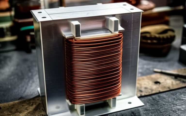
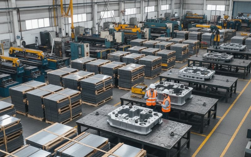
Sino의 라미네이션 스택으로 프로젝트에 힘을 실어주세요!
프로젝트 속도를 높이기 위해 라미네이션 스택에 다음과 같은 세부 정보를 레이블로 지정할 수 있습니다. 허용 오차, 재료, 표면 마감, 산화 단열재가 필요한지 여부, 수량등 다양한 기능을 제공합니다.
서류상으로는 “폭: 0-230mm, +0.00 / -0.20mm”가 무해해 보입니다. 허용 오차 표의 또 다른 줄에 불과합니다.
작업 현장에서는 동일한 라인이 차이점입니다:
CRGO 등급과 두께가 가장 많은 관심을 받습니다. 하지만 이미 저손실 등급을 구매하고 나면 공급업체의 슬릿 및 제어 방식이 달라집니다. 라미네이션 폭은 빌드 품질과 무부하 손실을 눈에 띄게 개선할 수 있는 몇 가지 수단 중 하나입니다. 공급업체들은 엄격한 폭 제어와 낮은 버를 핵심 차별화 요소로 강조합니다.
이 기사는 그 좁은 철조망에 머물러 있습니다: CRGO 라미네이션의 슬릿 폭 허용 오차. 코일에서 라미네이션 스택으로, 에어 갭으로, 마지막으로 와트 손실 및 자화 전류로 이동하는 방식입니다.
형식적인 정의는 이미 알고 계시니 실수로 고정해 보겠습니다.
일반적인 표준에 기반한 일반적인 라미네이션 허용 오차 차트에는 다음과 같은 내용이 명시되어 있습니다:
일부 공급업체는 +0/-x 대신 ± 값으로 대체로 유사한 대역을 인용하며, 원시 CRGO용 슬릿 코일 생산업체는 코일 폭 허용 오차(예: 코일 폭 0~+2mm)가 훨씬 더 느슨할 수 있습니다.
이렇게 하면 체인에 세 가지 다른 “너비 현실'이 생깁니다:
도면에는 보통 (3)에 대해서만 설명되어 있습니다. 공급업체의 프로세스 역량에 따라 (1)과 (2)가 스택으로 누출되는 양이 결정됩니다.

너비 허용 오차는 단순히 팔다리를 축소하거나 확장하는 데 그치지 않습니다. 중요한 세 곳에서 누수가 발생합니다:
림 라미네이션이 공차 하단을 향해 방황하는 반면 요크 라미네이션은 공칭에 가까워지면 스텝 랩 조인트가 깔끔하게 정렬되지 않습니다. 이해합니다:
라미네이션 품질에 대한 여러 기술 노트에서는 치수 오류(폭, 각도, 캠버)로 인해 원치 않는 에어 갭이 발생하여 단일 시트 테스트가 예측하는 것 이상으로 무부하 손실이 증가한다고 명시적으로 경고하고 있습니다.
단단한 클램핑에도 불구하고 실제 코어는 약간 탄성이 있는 시스템입니다. 한쪽 팔다리가 약간 더 좁은 라미네이션으로 제작되는 경우:
이는 조립 시간만 낭비하는 것이 아닙니다. 이러한 즉흥적인 수정은 종종 코어를 고정하고 응력을 가하는 방식을 변경하여 손실로 이어집니다.
다단계 랩 조인트에서는 라미네이션 패킷 간의 폭 차이로 인해 각 단계의 오버랩이 변경됩니다. 매끄러운 자기 경로 대신에:
좋은 스텝 랩 디자인은 스트립 너비가 일정하다고 가정합니다. 코일을 따라 더 많은 너비가 드리프트될수록 실제 조인트는 시뮬레이션한 디자인에서 더 많이 드리프트됩니다.
엔지니어들은 때때로 “-0.2mm 폭”이 플럭스 밀도를 급격히 높일까 봐 걱정합니다. 원시 면적 효과는 일반적으로 작습니다.
간단한 경우를 예로 들어보겠습니다:
면적은 너비에 따라 확장되므로
δa / a ≈ -0.2 / 250 = -0.08%
자속 밀도는 고정 전압과 회전수에 대해 동일하게 0.08%까지 올라갑니다. 약 1.7T의 코어 손실이 B^1.6으로 대략적으로 확장된다면, 이는 약 0.13% 더 많은 손실 너비 변화만으로는 알 수 없습니다.
따라서 폭 허용 오차로 인한 순수한 단면 변화는 큰 악당이 아닙니다..
악당들이 있습니다:
이는 단순한 ΔB 계산으로는 파악할 수 없으며, 조립 코어 손실이 단일 시트 테스트 손실을 초과하는 이유가 반복해서 호출됩니다.
체인을 좀 더 물리적인 방식으로 살펴봅시다.
허용 오차를 벗어난 너비는 다음과 상호 작용합니다:
요크가 약간 더 넓으면 스텝이 다리 스택을 넘어 돌출됩니다. 그러면 로컬 분리 클램핑은 몇 개의 라미네이션을 나머지 라미네이션보다 더 세게 부수지 않으면 완전히 닫히지 않습니다.
작은 틈새도 국부적 저항을 크게 증가시킵니다. CRGO 취급에 대한 기술 노트에 따르면 접합부의 잘못된 절단 각도와 형상 변화는 주로 이러한 추가 간격과 왜곡된 플럭스 경로를 통해 총 코어 손실을 내재적 시트 손실보다 몇 퍼센트 더 높일 수 있습니다.
너비 허용 오차는 이 장면의 조용한 공모자입니다.
폭 드리프트로 인해 스택이 약간 쐐기 모양인 경우 클램핑 빔이 각 라미네이션을 균등하게 로드하지 못합니다:
압력이 높으면 절연 코팅이 국부적으로 손상되어 층간 전류와 추가 와류 손실이 발생하고, 압력이 너무 낮으면 에어 포켓이 남을 수 있습니다. 동일한 CRGO 지침 문서에서 과도한 클램핑 압력과 표면 오염은 양호한 소재의 실제 손실 승수로 설명합니다.
폭 변화는 의도치 않게 스트레스 핫스팟과 콜드스팟을 만들 수 있는 한 가지 방법입니다.
슬리팅은 너비뿐만이 아닙니다. 이 공정에서는 잔류 응력도 발생하며 스트립 가장자리가 롤링 방향과 평행하지 않으면 유효 입자 방향이 약간 흐트러질 수 있습니다.
너비가 제대로 제어되지 않으면 보이는 경향이 있습니다:
그래서 실용적인 번들입니다: 일반적으로 예측하기 어려운 국소 자기 성능과 함께 제공되는 열악한 폭 제어 기능, 평균 코일이 여전히 P1.7/50 제한을 충족하는 경우에도 마찬가지입니다.
이제 모두가 계속 미루는 부분, 즉 실제로 무엇을 지정해야 하는가입니다.
아래는 실용적인 보기 일반적인 공차 표와 빌드 및 손실 발생 경향을 병합한 표입니다. 숫자는 예시용이지만 널리 공개된 라미네이션 공차 데이터를 기반으로 합니다.
| 라미네이션 폭 범위(mm) | 도면의 일반적인 “표준” 허용 오차 | 더 엄격한 관행이 인용될 수 있습니다. | 코어 빌드에서 일반적으로 의미하는 것 | 지오메트리로 인한 일반적인 손실 영향(정성적) |
|---|---|---|---|---|
| 0-100 | +0.00 / -0.15 | ±0.05 ~ ±0.10 | 소형 부품(션트, 소형 EI 코어). 제작은 보통 괜찮지만, 다른 코일의 스트립이 섞이는 것이 주요 위험입니다. | 손실은 대부분 무시할 수 있는 수준이며, 지오메트리 문제는 각도/캠버가 좋지 않은 경우에만 주로 발생합니다. |
| 100-230 | +0.00 / -0.20 | ±0.05 ~ ±0.10 | 배전 변압기의 LV 리브 및 요크에 일반적입니다. 서로 다른 슬릿의 코일이 혼합되면 폭 드리프트가 눈에 보이는 스텝 불일치로 표시되기 시작합니다. | 간격과 클램핑 방식에 따라 “양호한” 빌드와 “지저분한” 빌드 간에 몇 퍼센트의 손실이 발생할 수 있습니다. |
| 230-400 | +0.00 / -0.30 | ±0.10 | 큰 다리/요크에 사용됩니다. 스텝이 긴 경우, 팔다리/요크 패킷 사이에 0.3mm의 차이만 있어도 눈에 띄는 돌출이 발생합니다. | 여기서 폭 제어가 제대로 이루어지지 않으면 자화 전류와 노이즈가 순수 손실만큼 높아집니다. |
| 400-750 | +0.00 / -0.50 | ±0.10 ~ ±0.20(하이엔드 공급업체의 제품만 해당) | 큰 파워 코어, 긴 스텝 길이, 무거운 스택. 너비를 느슨하게 제어하면 빌드 시간, 쉬밍, 때로는 드로잉 변경이 필요합니다. | 동일한 소재 배치의 최고 스택과 최저 스택 간 손실 스프레드는 몇 퍼센트 차이가 날 수 있습니다. |
참고:
디자인에 대한 메시지: 두꺼운 팔다리와 긴 스텝은 느슨한 폭 조절로 인한 손상을 증폭시킵니다., 는 면적 변화가 커서가 아니라 지오메트리 오류가 누적되기 때문입니다.
구매는 플럭스 밀도를 선택하는 경우는 거의 없지만, 공급업체와 허용 오차 언어를 선택하는 경우는 절대적으로 많습니다.
디자인 파일을 건드리지 않고 할 수 있는 작업은 다음과 같습니다.
RFQ / PO 문서에서:
일부 공급업체는 공격적인 분류와 스크랩을 통해서만 라미네이션 허용 오차를 충족하지만, 이는 괜찮을 수 있지만 그 현실을 미리 알고 싶을 것입니다.
검사 보고서에서 한 줄의 “너비 확인” 대신 요청을 입력합니다:
모든 배송에 전체 SPC 차트가 필요하지는 않습니다. 분기별 또는 PPAP 스타일의 연구로 폭이 통제되는지 아니면 그냥 “검사”되는지 여부를 노출하는 것으로 충분합니다.
너비 허용 오차 자체는 다음과 같은 경우를 제외하고는 유용하지 않습니다:
구매 사양은 관련 없는 4개의 글머리 기호가 아닌 하나의 클러스터로 취급해야 합니다.
엔지니어링 관점에서 보면 세 개의 노브가 있습니다:
앞서 살펴본 바와 같이 300mm 사지 폭에서 최악의 경우 -0.3mm만 발생해도 0.1%의 면적 변화가 발생합니다. 이것만으로는 무부하 손실에 대한 5-10%의 설계 마진을 정당화할 수 없습니다.
따라서 B를 임시 마진으로 크게 부풀리는 대신 이렇게 하는 것이 더 현실적입니다:
단일 시트 테스트 데이터는 아첨입니다. 실제 코어는 어려움을 겪습니다:
목표 코어 손실을 선택할 때
너비 허용 오차 제어는 이 “가산기'를 조이는 하나의 레버입니다.
허용 오차를 좁힐수록 어딘가에서 비용이 발생합니다(스크랩, 느린 절단, 더 나은 칼, 더 많은 수표). 일반적으로 언제 강화할 가치가 있습니다:
코어가 기존 손실 보증에 미치지 못하는 경우, 폭 허용 오차가 가장 먼저 해결해야 할 병목 현상은 거의 없습니다. 등급, 두께, 버, 조립 공정부터 시작하세요.
계측 실험실은 필요하지 않습니다. 기본적인 루틴만 있으면 됩니다:
많은 공급업체가 이미 30분마다 유사한 점검을 실시하고 있으며, 몇몇 공급업체는 각 기계에서 폭, 버, 캠버 및 두께와 같은 매개변수를 모니터링한다고 공개적으로 밝히고 있습니다.
공급업체가 해당 데이터 공유를 거부하는 경우, 이는 자체적인 측정 방식입니다.
팔다리 및 요크 너비의 경우 100-300mm 범위, 일반적인 라미네이션 차트가 제공합니다:
최대 230mm 너비의 경우 +0.00 / -0.20mm입니다,
+0.00 / -0.30mm 최대 ~400mm.
일반적으로 표준 배포 설계에는 이 정도면 충분합니다. 만약 버, 캠버 및 각도도 제어됩니다. 엄격한 손실 또는 노이즈 보장이 필요한 경우 다음을 요청하세요. 대칭 ±0.10 mm (기능의 증거가 있는) 임계 폭에 대한 합리적인 업그레이드입니다.
항상 그런 것은 아닙니다. 특정 지점 이하에서는 손실 및 노이즈의 주요 원인이 됩니다:
CRGO 등급 자체,
라미네이션 두께,
조인트 설계 및 조립 품질.
코어가 정기적으로 손실 목표치를 10% 이상 놓치는 경우 너비를 가장 먼저 강화해야 할 대상은 아닐 것입니다. 너비 허용 오차를 미세 조정 도구 기본 사항이 통제되면.
왜냐하면 오버사이즈 라미네이션은 즉각적인 기계적 문제를 일으킵니다:
코일 삽입의 어려움,
프레임 및 클램핑 플레이트와의 정렬이 잘못되었습니다,
조립 중 강제 구부러짐의 위험이 증가합니다.
크기가 약간 작을수록 생활하기가 더 쉽기 때문에(플럭스 밀도에서 약간의 페널티를 지불하고 더 많은 시밍을 할 수도 있습니다) 많은 라미네이션 공차 테이블은 공칭 너비에서 음의 편차만 허용합니다.
줄어들긴 했지만 사라지지는 않습니다.
상처 코어용:
스트립 너비는 일반적으로 전체 코어에 대해 일정합니다,
같은 의미의 마이터 조인트가 없습니다,
빌드는 작은 폭 편차보다 가장자리 품질과 내부 응력에 더 민감합니다.
따라서 여기서 좋은 너비 제어의 주요 역할은 다음과 같습니다:
상처 코어가 디자인된 창과 프레임과 일치하는지 확인합니다,
절단 지점이나 관절에서 “계단” 효과를 피합니다,
스트레스 분포를 균일하게 유지합니다.
가끔씩만요.
손실 폭이 크지 않고(몇 퍼센트) 다음과 일치하는 경우:
새로운 라미네이션 공급업체,
관절 접촉이 악화됩니다,
핵심 빌드에 더 많은 재작업이 필요합니다,
그렇다면 슬릿 폭 제어가 에어 갭과 응력을 통한 원인 중 일부일 수 있습니다.
손실 점프가 큰 경우(10-20%) 먼저 다음을 살펴보세요:
등급이나 두께가 조용히 변경되었는지 여부를 확인합니다,
클램핑 연습이나 어닐링이 변경되었는지 여부를 확인합니다,
취급 중 라미네이션이 손상되었거나 오염되었는지 여부를 확인합니다.
너비 허용 오차만으로는 매우 큰 점프를 설명하는 경우는 거의 없습니다.
안정적이고 감사를 받은 공급업체를 위해:
최초 승인 시 한 번만 입력합니다,
그런 다음 대략 매년 또는 슬리팅 장비, 툴링 또는 공정 경로를 변경할 때마다.
이를 공장의 지속적인 입고 검사와 결합하여 공식적인 연구 사이에 드리프트를 잡을 수 있습니다.