Sino의 라미네이션 스택으로 프로젝트에 힘을 실어주세요!
프로젝트 속도를 높이기 위해 라미네이션 스택에 다음과 같은 세부 정보를 레이블로 지정할 수 있습니다. 허용 오차, 재료, 표면 마감, 산화 단열재가 필요한지 여부, 수량등 다양한 기능을 제공합니다.
이 글의 내용 CRGO 라미네이션 스택 vs 나노 결정 코어, 를 디자인 + 구매 관점에서 살펴보세요.
기본 사항은 이미 알고 계실 겁니다:
데이터 시트에는 약간 다른 글꼴로 비슷한 내용이 적혀 있습니다. 문제는 실제 코어와 라미네이션 스택을 구축할 때 어떻게 작동하는지, 그리고 각 선택이 실제로 어떤 이점을 가져다주는지 알아보세요..
일반적인 카탈로그 값을 한 페이지에 넣어 보겠습니다. 다음은 다음과 같습니다. 야구장 엔지니어링 수치, 디자인 제한이 아닙니다.
| 매개변수(일반) | CRGO 라미네이션 스택 | 나노 결정 테이프 권선 코어 |
|---|---|---|
| 포화 플럭스 밀도 B | ≈ 1.8-2.0 T | ≈ 1.2-1.3 T |
| 상대 투과성 µr(사용 가능한 범위) | ≈ 30,000-50,000 | ≈ 80,000-150,000(조정 가능, 더 높을 수도 있음) |
| 코어 손실 @ 50Hz, 1.7T | ≈ 0.9-1.6W/kg(로우엔드에서 Hi-B) | 보통 50Hz로 그렇게 세게 실행하지 않습니다. |
| 코어 손실 @ 20kHz, 0.1T | >150W/kg | <15W/kg |
| 퀴리 온도 | ≈ 730-750 °C | ≈ 550-580 °C |
| 전기 저항 | ≈ 40-50 μΩ-cm | ≈ 100-120 μΩ-cm |
| 일반적인 스태킹/라미네이션 계수 | 스텝 랩 스택이 양호한 경우 ~0.96 | 상처 리본의 경우 ~0.75-0.80 |
| 스위트 스팟 주파수 대역 | 50/60Hz, 최대 수백 Hz | 수 kHz에서 최대 수십 kHz(플럭스에 따라 다름) |
| 실제 기하학 | EI, 스텝 랩 코어, 상처 다리, 리액터 | 토로이드, 컷 코어, C-코어, 특수 스택 |
| kg당 상대적 재료비 | Lower | 더 높음 |
| 상대 전력 밀도 잠재력 | 높은 f에서의 손실로 인한 제한 | 중간 주파수 범위에서 매우 강함 |
위의 데이터는 하나의 마케팅 시트가 아닌 핵심 공급업체의 게시된 사례와 자료 노트를 병합한 것입니다.
몇 가지 눈에 띄는 점이 있습니다:
이 두 가지 사실은 이미 각각의 승자가 어디에서 승리할지 암시합니다.
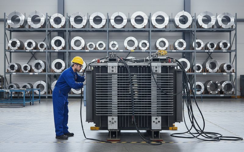
다음을 수행 중인 경우 MV/HV 전력 또는 배전 변압기 그리드 주파수에서 메인 코어의 경우 거의 확실하게 CRGO 라미네이션을 사용하고 있습니다:
1 MVA 50Hz 장치의 경우, 메인 다리를 나노 결정으로 전환하는 것은 일반적으로 시작하지 않는 것이 좋습니다:
따라서 클래식 전력 변압기, CRGO 라미네이션 스택은 다음에서 큰 차이로 승리합니다. kVA당 비용, 실용성 및 생태계를 고려합니다.
사양에서 냄새가 날 때마다:
...다음과 같은 기능이 있습니다. ~1.9-2.0 T 채도 대신 ~1.25T.
나노 결정은 특수한 경우에 높은 유도를 처리할 수 있지만 요점은 간단합니다: 오류 발생 시 코어가 한계 근처에 있는 경우 일반적으로 CRGO가 더 안전합니다..
빅 코어에서:
이러한 크기의 나노 결정 코어(단순한 토로이드가 아닌 적층 나노 스택)는 존재하지만, 공급업체가 적고 공정 기간이 촉박한 특수 품목입니다.
구매 팀이 원하는 경우 두 번째 및 세 번째 소스 모든 전략적인 부분에서 CRGO 스택은 삶을 더 단순하게 만들어줍니다.
이제 흥미로운 부분입니다. CRGO가 기술적으로는 가능하지만 현명하지는 않은 곳입니다.
생각해보세요:
그 밴드에서, CRGO 코어 손실이 폭발적으로 증가. 나노크리스탈은 침착함을 유지합니다:
따라서 기본 또는 지배적 스위칭 주파수 는 5~50kHz 영역에 있고 전력이 작지 않으며, 일반적으로 페라이트가 아닌 나노 결정이 선두 주자이며 CRGO가 아닙니다.
공통 모드 초크와 EMI 필터는 전형적인 나노 결정 영역입니다:
CRGO를 사용하면 둘 중 하나를 선택할 수 있습니다:
따라서 BoM에 여러 개의 대형 페라이트 CM 초크가 있는 경우, 나노 결정질 테이프 권선 코어로 교체하는 것이 가장 쉬운 밀도 업그레이드인 경우가 많습니다..
For 변류기(CT) 및 정밀 기기 변압기:
드라이브, EV 충전기, UPS 출력과 같은 왜곡된 파형을 CT에서 발견하면 나노 결정 코어는 실리콘 스틸이 방황하기 시작하는 비율과 위상 정확도를 유지하는 경향이 있습니다.
때로는 기본값이 여전히 50/60Hz이지만:
여기, 나노 결정은 “하나의 재료에 CRGO + 필터 페라이트”처럼 작동합니다.”. :
이것이 바로 최신 건식 변압기와 전력 전자 제품을 겨냥한 특수 원자로에서 나노 결정체를 볼 수 있는 이유 중 하나입니다.
엄격한 규칙이 아닙니다. 조기 선발을 위한 정신 상태 점검일 뿐입니다:
디자인이 경계에 정확히 놓여 있다면 하나의 “정답'이 아닌 반복을 기대하세요.
부품 수준에서는 나노 결정이 비싸 보일 수 있습니다. 하지만 시스템 수준, 를 계산하면 됩니다:
...특히 중간 주파수 변환기에서 처리하는 kW당 더 저렴하게 착륙할 수 있습니다.
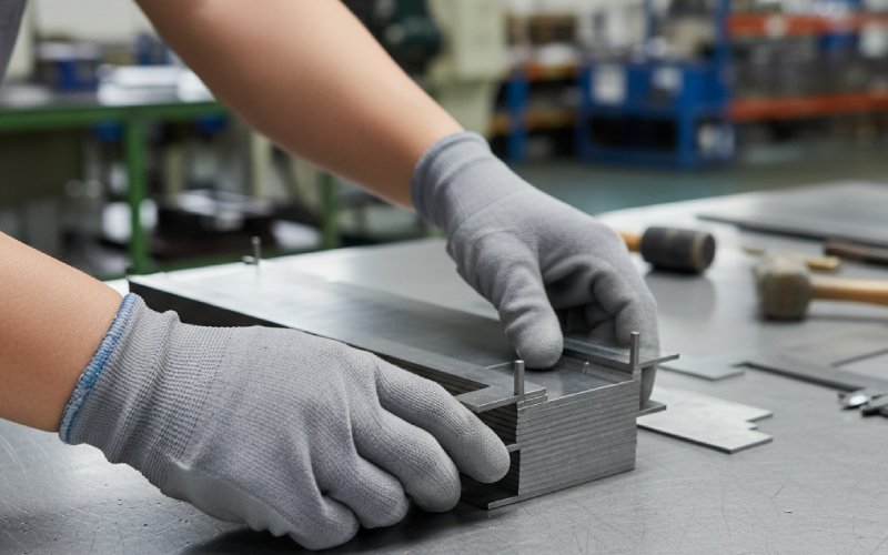
CRGO 스트립 및 라미네이션:
나노 결정체:
프로젝트가 안전이 중요하거나 수명이 긴 경우 다음과 같이 설계하는 것이 좋습니다. 기계식 봉투 및 라미네이션 스택 창 하나의 독점 부품이 아닌 최소 두 개의 나노결정 코어 형상을 수용할 수 있습니다.
데이터 시트에는 나와 있지 않지만 수익률에 영향을 미칩니다.
나노 크리스탈 리본입니다:
과도한 클램핑 또는 고르지 않은 압력이 발생할 수 있습니다:
상처 코어를 다음과 같이 처리하도록 클램핑 방식을 설계하십시오. 정밀 구성 요소, 를 사용하여 무거운 라미네이션을 쌓아 올리는 것이 아닙니다.
라미네이션 스택의 경우:
따라서 몇 퍼센트 단위의 효율성을 추구하는 경우, 핵심 공장 공정 제어는 재료 등급만큼이나 중요합니다..
부하가 드라이브 캐비닛인 경우 설계에 “50Hz 변압기'라고 표시되는 경우가 있습니다:
이 경우:
몇 가지 직설적인 질문으로 자료 선택의 타당성을 점검할 수 있습니다.
물론 두 가지를 혼합할 수도 있습니다: 동일한 제품에 CRGO 메인 라미네이션 스택 + 나노결정 CT 및 CM 초크를 사용하는 것은 이미 최신 스위치 기어 및 전력 컨버터에서 일반적입니다.
보통은 아닙니다.
나노크리스탈린은 다른 플럭스 밀도, 다른 창 활용도, 그리고 종종 다른 냉각 전략.
직접 일대일 교환은 코어를 포화시키거나 소재를 적게 사용하는 경향이 있습니다.
나노 결정의 이점을 원한다면 교체용 라미네이션 등급이 아닌 새로운 마그네틱 디자인으로 취급하세요.
예, 하지만 상품 부품은 아닙니다.
연구원 및 일부 제조업체는 적층 나노 결정 코어 표준 토로이드가 맞지 않는 고주파 전력 전자 장치에 주로 사용되는 처리된 리본이나 테이프 커팅 타일을 쌓아 올리는 방식입니다.
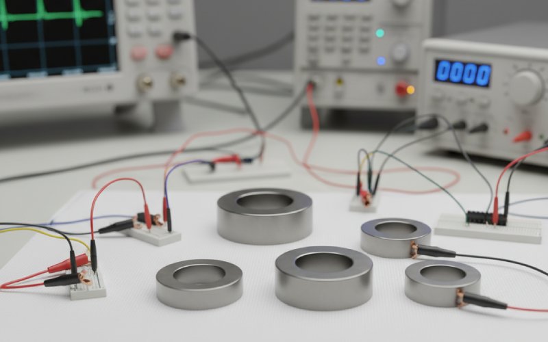
하지만 현재로서는 대부분의 상용 나노 결정 부품을 볼 수 있습니다:
토로이드(솔리드 또는 컷)
C-코어
특수 상처 모양
귀하의 비즈니스가 고전적인 전력 변압기인 경우, 당분간은 여전히 CRGO 라미네이션 스택을 주로 사용하게 될 것입니다.
높은 수준에서:
둘 다 훨씬 낮은 손실 보다 더 많은 코어 손실을 줄입니다. 비정질은 많은 경우 기존 실리콘 스틸에 비해 코어 손실을 최대 ~70%까지 줄일 수 있습니다.
나노 결정은 종종 비정질에서 다음과 같이 개선됩니다. 더 높은 주파수, 는 투과성이 높고 수십 kHz 대역에서 손실이 적습니다.
그래서:
대용량의 초고효율 50/60Hz 배전 변압기: 아몰퍼스 및 고급 GOES가 경쟁합니다.
중주파 자기 및 EMI의 경우: 나노 결정체가 유리한 경향이 있습니다.
때로는 그렇습니다.
100kHz에서 20~50W 플라이백의 경우:
페라이트는 저렴하고 간편하며 충분히 좋은 제품입니다.
나노 결정은 전력, 전류 또는 DC 바이어스가 증가하거나 크기가 심각하게 제한될 때 더욱 의미가 있기 시작합니다.
EMI 및 효율 목표가 까다로운 고전력 SMPS(kW급)에 적합합니다, 나노 결정 변압기 및 초크 는 강력한 지렛대가 될 수 있습니다.
일반적으로 세 가지 짧은 요점이 도움이 됩니다:
변환기 수준에서, 강철보다 손실 및 냉각 비용이 더 많이 듭니다.. 코어 손실이 적으면 히트싱크, 팬 또는 액체 냉각 요구 사항을 줄일 수 있습니다.
더 높은 투과성은 다음을 의미합니다. 구리 감소, 더 적은 회전 수, 때로는 더 저렴한 PCB 및 조립.
많은 프로젝트에서 마그네틱 부피와 무게는 이제 BoM의 라인 항목이 아니라 시스템 수준의 제약 조건(랙 공간, 차량 패키징)이 되었습니다.
그래도 착륙이 되지 않으면 간단한 와트당 비용 절감 CRGO와 나노 결정체 디자인을 비교합니다. 숫자는 조용하지만 명확하게 말하는 경향이 있습니다.
CRGO 라미네이션 스택은 사라지지 않습니다. 대형 저주파 변압기 및 고장 조건에서 높은 자속으로 작동하는 모든 제품에 탁월한 성능을 발휘합니다.
나노 결정 코어도 마법이 아닙니다. 나노 결정 코어는 장단점을 한 번만 유리하게 바꿀 뿐입니다:
둘 다 팀이 아닌 도구로 취급하고 적절한 주파수 대역과 업무에 맞게 조정하면 다음과 같은 이점을 얻을 수 있습니다. 라미네이션 스택, 권선 코어 및 구매 결정 가 모두 훨씬 더 쉽게 정렬되기 시작할 것입니다.