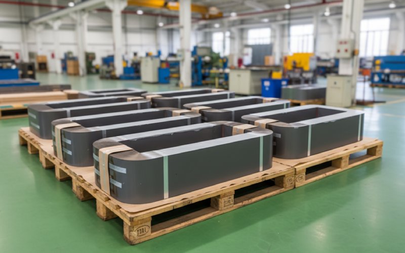
Laat Sino's lamineren Stacks Empower uw project!
Om je project te versnellen kun je lamineerstapels labelen met details zoals tolerantie, materiaal, oppervlakafwerking, of geoxideerde isolatie al dan niet vereist is, hoeveelheiden meer.
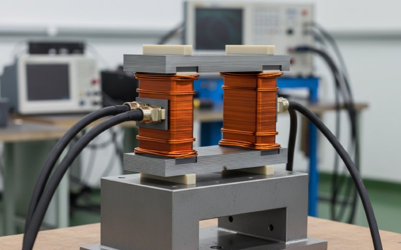
Veel CRGO-laminering De inhoud gaat rustig uit van een bijna-sinusvormige spanning en een schone magnetisatielus. Reactoren en veel spoelen leven daar niet.
Korrelgeoriënteerd staal gedraagt zich onder deze omstandigheden anders dan in de 50/60 Hz, sinusgolftest die in standaard verliesclassificaties wordt gebruikt. Een recent onderzoek naar GOES gewikkelde kernen bij ~2 kHz toont zelfs specifieke verliezen lager voor kwadratische spanningen dan voor quasi-sinus bij dezelfde piekflux, omdat de harmonische inhoud verschuift waar wervelstromen zich concentreren in de strip.
Dus voordat je uit gewoonte kiest voor “M3, 0,27 mm”, moet je je eerst vergrendelen:
Al het andere - stapelfactor, stijl van de verbinding, gap-schema - hangt af van die vier.
Datasheets vermelden graag verzadiging rond 1,9-2,0 T voor elektrisch staal met georiënteerde korrel, met een redelijk lineair gebied tot ruwweg 1,2 T.
In de praktijk wil je voor vermogensreactoren en spoelen met ijzeren kern zelden zo dapper zijn.
Deze zijn indicatief, geen vervanging voor je eigen B-H curves en levensduurmodel:
| Type toepassing | Typisch ontwerp Bpiek in CRGO | Commentaar op marge |
|---|---|---|
| Shuntreactor (HV, oliebad) | 1.1 - 1.4 T | Sterke focus op verlies + hotspotcontrole |
| Lijnreactor (LV/MV) | 1.0 - 1.3 T | Bekijk DC bias van converters |
| DC-smoorspoel (AC/DC-front-end) | 0,8 - 1,1 T (rond DC-bedrijfspunt) | Flux offset domineert; kloof is het belangrijkste gereedschap |
| Spoel voor middenfrequentie (enkele kHz, CRGO) | 0.8 - 1.2 T | Afweging tussen grootte en kernverlies |
| Eenvoudige netsmoorspoel | 1.2 - 1.5 T | Vaak koperbeperkt in plaats van kernbeperkt |
Een klassieke ontwerpgids voor gesneden kernen voor korrelgeoriënteerd staal laat een bruikbaar “lineair genoeg” gedrag zien tot ~1,2 T, zelfs onder DC-bias als de spleet correct wordt gekozen.
Voor lijn- en shuntreactoren, Je komt meestal dichter bij de transformatorpraktijk, maar:
Voor spoelen in schakelende voedingen, accepteer je normaal gesproken een lagere Bpiek omdat:
Vuistregel die projecten uit de problemen houdt: Ontwerp eerst tegen Bmax,heet,bevooroordeeld, niet op kamertemperatuur Bmax. Controleer dan of het cijfer dat je wilde nog steeds zinvol is.
Iedereen schrijft “stapelfactor 0,96” op de dia. De werkelijkheid is rommelig.
Stapelfactor heeft rechtstreeks invloed op de effectieve ijzerdoorsnede. Lagere factor → minder staal → hogere fluxdichtheid dan je dacht → vroege verzadiging en extra verlies. Een standaard magneetkernhandboek wijst erop dat verkeerd uitgelijnde bramen en slechte isolatie tussen de lamineringen de stapelingsfactor gemakkelijk genoeg kunnen uithollen om van belang te zijn op vermogensniveaus waar CRGO wordt gebruikt.
Belangrijkste punten:
Voor reactorkernen, De stapelfactor is iets vergevingsgezinder dan bij hoogrendementstransformatoren, omdat veel ontwerpen al gap-dominated zijn. Maar zodra je HV shuntreactoren met hoge flux en laag verlies gaat gebruiken, worden kleine fouten in het effectieve oppervlak zichtbaar als extra watt en onverwachte hotspotlocaties.
Je hoeft dit niet allemaal in de RFQ te zetten, maar ontwerp eromheen:
Als je een transformatorlamineergereedschap opnieuw gebruikt voor een reactor, controleer dan of de Echt of de stapelhoogte na het coaten en persen nog overeenkomt met het magnetische ontwerp. Vaak is dat niet zo.
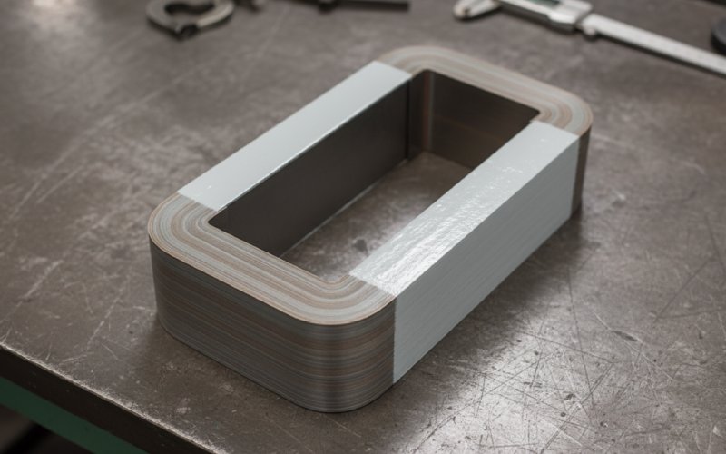
CRGO laminaat blogs besteden veel tijd aan step-lap voor transformatoren. De fysica is ook van toepassing op reactoren en inductoren, alleen met andere prioriteiten.
In reactoren:
Welke verbinding je ook gebruikt, zorg ervoor dat je tekening en RFQ hierover gaan:
Als u de gezamenlijke strategie “impliciet” laat, eindigt dit vaak met het gebruik van de standaard transformator van de leverancier, die mogelijk niet past bij de DC-bias en golfvorm van uw reactor.
Hiaten zijn de plaatsen waar reactorkernen stilletjes extra verlies genereren.
Academisch werk aan shuntreactoren met ijzeren kern en discreet verdeelde luchtspleten vergelijkt:
Het laat zien hoe het verdelen van de spleet inductantie, lekinductantie en verlies afzonderlijk kan aanpassen en hoe franje rond elke spleet lokaal wervelstroomverlies toevoegt.
Voor vermogensreactoren leidt dit tot een paar ontwerphefbomen:
Voor spoelen wordt in een klassieke ontwerpgids voor ijzeren kernen de nadruk gelegd op C-kernen:
Laat de geometrie van gaten dus niet vaag.
En nee, de zin “typical transformer gap practice” in de specificaties is niet voldoende als je reactor dicht bij verzadiging moet werken onder DC bias.
De meeste artikelen over ruis zijn gericht op transformatoren, maar dezelfde magnetostrictieverschijnselen doen zich voor in grote reactoren en spoelen: lamellen rekken lichtjes uit als de flux omkeert en de stapel trilt.
In recente technische aantekeningen over CRGO magnetostrictie worden een aantal punten genoemd die rechtstreeks van toepassing zijn op reactor- en inductorstapels:
Voor reactoren:
Ontwerpcontrolelijst voor de stapel:
CRGO heeft een redelijk hoge thermische geleidbaarheid en een hoge Curietemperatuur (vaak rond 730 °C voor standaardkwaliteiten).
Twee gevolgen die van belang zijn in reactoren/inductoren:
Voor het ontwerp van lamineerstapels:
Thermisch gezien zal CRGO je meestal vergeven. Het isolatiesysteem van de wikkeling niet.
De meeste RFQ's specificeren kwaliteit, dikte en coating, Misschien “step-lap”. Normengidsen wijzen erop dat kwaliteitscodes en tabellen met verliezen maar de helft van het verhaal vertellen; de rest zit in hoe de lamineringen tot een kern worden gemaakt.
Voeg voor reactoren en inductoren wat precisie toe.
Specificeer:
Omvatten:
Voor CRGO kernen met gaps:
Je hebt geen miljoen tests nodig. Maar definieer een kleine, duidelijke set:
Op deze manier kunt u, als een reactor later heet wordt of vroegtijdig verzadigd raakt, dit terugvoeren op ontwerpaannames of stackuitvoering, zonder te hoeven gissen.
Niet uitputtend, maar het vangt veel van de problemen op die laat opduiken:
Als een antwoord “niet zeker” is, is dat meestal waar toekomstige faalanalyses vandaan komen.
Soms, maar niet blindelings.
Als de lijnreactor vergelijkbare fluxniveaus heeft en geen ernstige DC bias, kan een transformatorachtige kern met step-lap verbindingen en vergelijkbare gradatie werken.
Zodra er DC bias of grote harmonische stromen optreden, heb je meer speling nodig en vaak een lagere Bmax. Dat verandert de optimale staalsoort en stapelhoogte.
Voer het ontwerp minimaal opnieuw uit met realistische stroomgolfvormen en stapelfactoren en controleer de spleetbepalingen.
Voor vroege schattingen:
0,95 is een goed uitgangspunt voor modern dun CRGO met goede coatings en vertrouwde stempels.
Verlaag naar 0,92-0,93 als het gereedschap oud is, de dikte >0,30 mm of de braamcontrole slecht is.
Maar ga over op gemeten waarden (via massa of afmetingen) zodra je de eerste artikelen hebt.
Korrelgeoriënteerd staal wint meestal wanneer:
Fluxdichtheid is hoog (0,8-1,2 T-gebied)
De frequentie is matig (tot een paar kHz)
Het vermogen is groot, dus het ferrietvolume zou te groot zijn
Ferrieten en poederkernen winnen het in het hoogfrequente domein, waar kernverliezen in CRGO zelfs bij lagere inductie te groot zijn. Het komt neer op frequentie vs Bmax vs volume vs verlies.
Bramen beïnvloeden:
Stapelfactor (minder effectief ijzer)
Interlaminaire wervelstromen (meer verlies)
De ontwerpliteratuur laat zien dat slecht beheerde bramen de stapelfactor voldoende kunnen verlagen om een zogenaamd “veilig” ontwerp in de richting van verzadiging te duwen.
Als je reactoren met een hoog vermogen ontwerpt, is het de moeite waard om een numerieke limiet voor de braamhoogte in de RFQ op te nemen en om een eenvoudige meetmethode te vragen (profilometer, steekproefcontroles per batch).
Dat kan, maar niet automatisch.
Onderzoeken naar shuntreactoren met discreet verdeelde gaten tonen aan dat:
Door spleten te verdelen kunnen inductantie en lekinductantie flexibeler worden geregeld.
Een rand rond elke spleet voegt lokaal wervelstroomverlies toe, dus te veel spleten kunnen het totale kernverlies verhogen als ze slecht worden geïmplementeerd.
Gedistribueerde spleten zijn dus een ontwerptool, geen gratis upgrade. Ze moeten ondersteund worden door een analyse (analytisch of FEA) en duidelijk gedimensioneerd worden voor de lamineerleverancier.
Vermijd voor CRGO-reactoren en inductoren dat deze items vaag blijven:
Gezamenlijke methode en overlap
Afmetingen en verdeling van de kloof
Bereik doelstapelfactor
Testomstandigheden kernverlies (B, f, temperatuur, golfvorm)
Die vier niet-beslissingen zorgen voor de meeste verrassingen als het prototype in de testruimte staat.