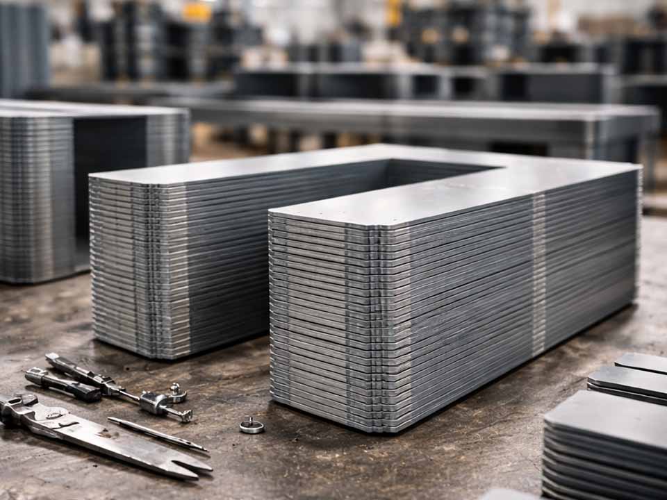
Deje que las pilas de laminación de Sino potencien su proyecto.
Para agilizar su proyecto, puede etiquetar las pilas de laminación con detalles como tolerancia, material, acabado superficial, si se requiere o no aislamiento oxidado, cantidady mucho más.
Medición del espesor del recubrimiento en laminados: explicación de los medidores de corrientes parásitas
Resumen ejecutivo
Los medidores de corrientes parásitas pueden medir el espesor del recubrimiento en laminaciones rápidamente, pero no por ello son automáticamente la herramienta adecuada para cualquier trabajo de laminación. El problema principal es el sustrato. Muchos motores, generadores y laminados para transformadores están fabricados con acero eléctrico magnético, mientras que los medidores de recubrimiento por corrientes parásitas estándar suelen estar diseñados para recubrimientos no conductores sobre metales conductores no magnéticos.
En el caso del acero eléctrico magnético, la inducción magnética suele ser el principio más directo para determinar el espesor del recubrimiento. Los métodos de corrientes parásitas pueden seguir funcionando en determinadas configuraciones, especialmente con sondas adecuadas y una validación previa, pero no deben considerarse como soluciones «plug-and-play».
La respuesta práctica es bastante sencilla: Elige el principio de medición en función del sustrato, comprueba su validez con el material de laminación concreto, realiza la medición antes del apilado siempre que sea posible y nunca confundas el espesor del recubrimiento con el rendimiento del aislamiento.
Esa es la versión «limpia». La versión «de taller» es más caótica.
Índice
Por qué es importante el espesor del recubrimiento en las pilas de laminación
El recubrimiento de laminación es fino. A veces, solo mide unos pocos micrómetros. Por eso es fácil subestimarlo.
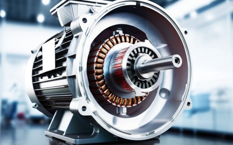
El recubrimiento ayuda a separar las chapas metálicas de una pila. Esta separación reduce las vías de corriente interlaminares, favorece el aislamiento eléctrico, limita la corrosión e influye en la estructura de la pila. Si el recubrimiento es demasiado fino, pueden producirse cortocircuitos locales entre las laminaciones. Si es demasiado grueso, el factor de apilamiento puede disminuir, ya que una menor parte de la altura de la pila corresponde a acero magnético útil.
También existe ese caso intermedio un tanto complicado: el recubrimiento tiene un aspecto aceptable en general, pero es débil cerca de los bordes troquelados, las rebabas, las ranuras o las zonas de presión. Ahí es donde suelen comenzar los fallos. No precisamente en el centro de una probeta plana. Suelen aparecer en la parte del laminado que nadie ha medido.
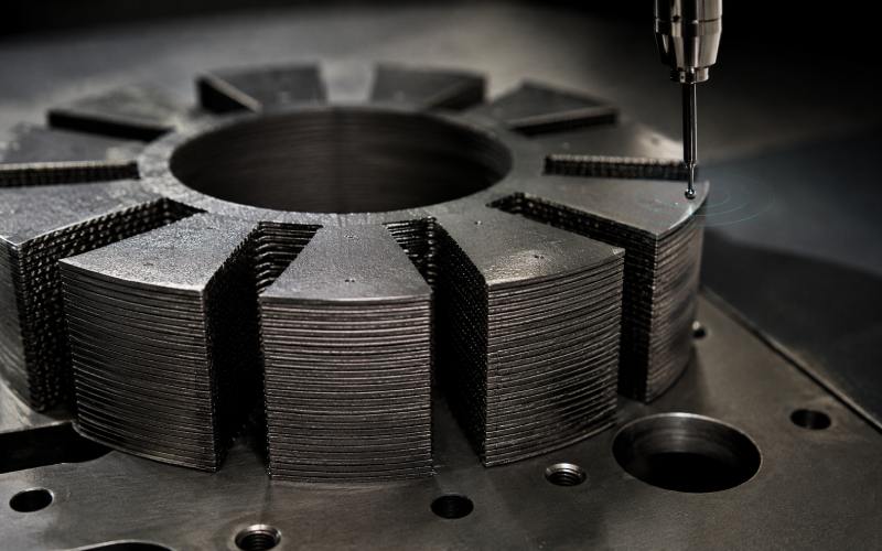
Cómo miden el espesor de los recubrimientos los medidores de corrientes de Foucault
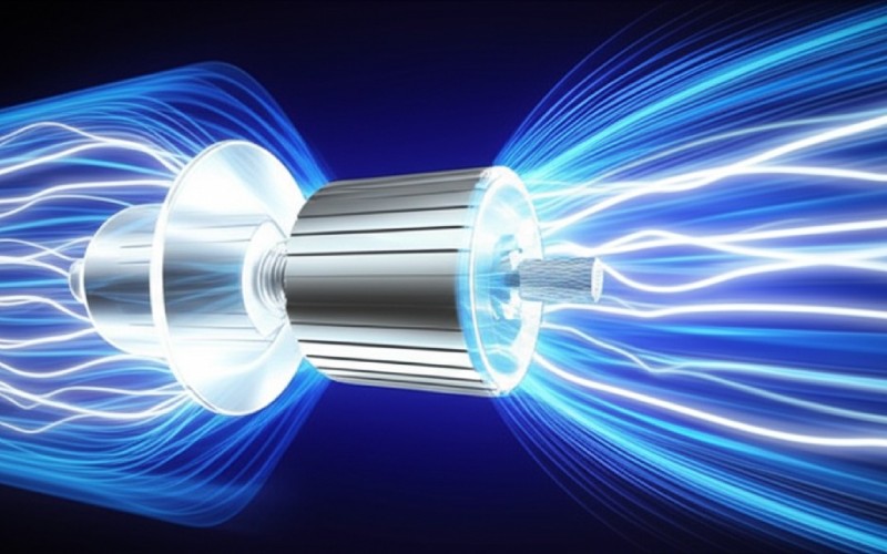
Un medidor de corrientes parásitas utiliza una bobina de sonda por la que circula corriente alterna. La sonda genera un campo electromagnético. Cuando la sonda se acerca a un material base conductor, ese campo induce pequeñas corrientes circulantes en el metal.
El recubrimiento modifica la distancia entre la sonda y el sustrato conductor. Este cambio en la distancia altera la señal de la sonda. El medidor convierte esa señal en espesor del recubrimiento.
Esa explicación se aplica a muchos casos sencillos: un recubrimiento no conductor sobre una base conductora no magnética.
Las laminaciones no siempre son tan sencillas.
El acero eléctrico es conductor y magnético. Su comportamiento magnético afecta a la señal de la sonda, a veces de forma considerable. Un medidor puede indicar el desprendimiento del recubrimiento, la permeabilidad del sustrato, los efectos del espesor de la chapa, la rugosidad de la superficie o una combinación de los cuatro factores. Aunque la cifra que aparece en la pantalla parezca estable, es posible que se esté midiendo un parámetro erróneo.
Corrientes parásitas frente a inducción magnética en el acero eléctrico
Esta es la parte que muchas guías sobre el espesor de los recubrimientos omiten, pero es importante.
En el caso de los recubrimientos de laminación, el principio de medición debe seleccionarse en función del par de materiales: recubrimiento más sustrato.
Estado del sustrato y del recubrimiento
Método habitualmente adecuado
Por qué
Advertencia principal
Recubrimiento no conductor sobre un metal conductor no magnético
Corrientes parásitas
La sonda detecta cuando se separa de la base conductora
No es el caso habitual de las láminas de acero eléctrico
Recubrimiento no conductor sobre acero magnético
Inducción magnética
La sonda detecta la distancia respecto a una base ferromagnética
Se recomienda validarlo con muestras reales de laminación
Recubrimiento muy fino sobre acero eléctrico magnético
Inducción magnética o sistema especializado y validado de corrientes parásitas
Las pequeñas variaciones de espesor son sensibles a los errores de calibración
No te fíes únicamente de la calibración de fábrica
Recubrimiento conductor o semiconductivo
Método especializado o verificación de referencias
Las hipótesis estándar pueden resultar erróneas
Confirmar con datos de ensayos de sección transversal, basados en la masa o eléctricos
Pila de laminados terminados
Solo medición de superficies limitadas
El estado del revestimiento interior no se aprecia a simple vista
Las lecturas externas no demuestran que exista aislamiento interlaminar
Un error habitual es preguntar: “¿Puede un medidor de corrientes parásitas medir esto?”.”
La mejor pregunta es: ¿Qué respuesta electromagnética utiliza realmente el medidor? ¿Se ha comprobado esa respuesta en este acero eléctrico recubierto?
Los medidores de corrientes parásitas sensibles a la amplitud pueden verse afectados por los cambios de permeabilidad en los sustratos magnéticos. Los instrumentos sensibles a la fase o de método dual pueden separar algunos de estos efectos, pero solo dentro del rango para el que han sido diseñados. La inducción magnética suele ser el punto de partida más seguro para los recubrimientos no magnéticos sobre laminaciones ferromagnéticas.
Aun así, no te bases solo en la teoría. Compruébalo.
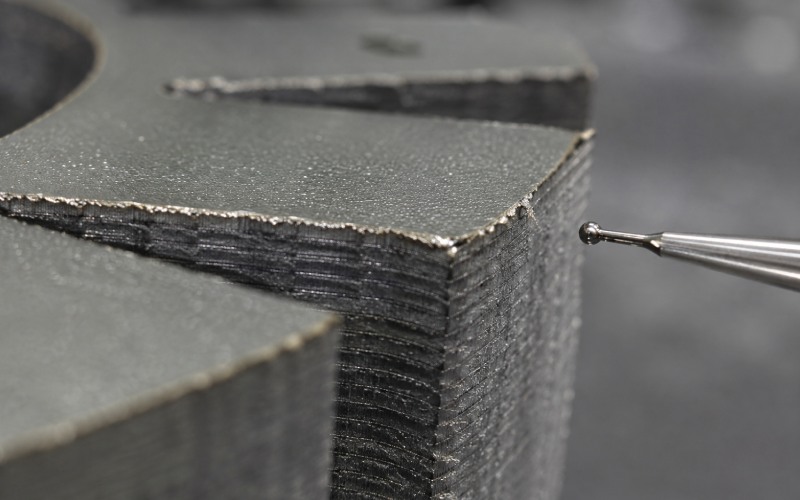
Retos de medición en las pilas de laminación
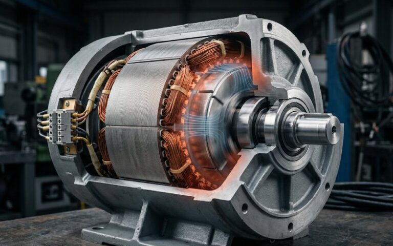
Un cupón plano y sin perforar es fácil de manejar. Uno laminado y perforado resulta menos práctico. Y una pila de cupones ya procesados es aún peor.
Las laminaciones plantean varios problemas de medición a la vez:
espesor de la lámina delgada
recubrimiento en una o ambas caras
rebabas de punzonado
grietas en los bordes o acero al descubierto
zonas curvadas o deformadas
rugosidad superficial
encajes, soldaduras, uniones o compresión
puentes estrechos entre las ranuras
recubrimientos modificados mediante tratamiento térmico
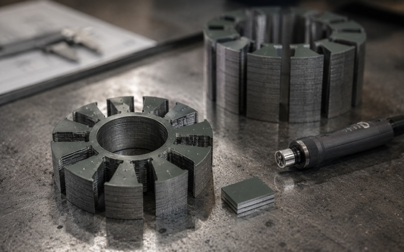
La lectura de un medidor en la parte exterior expuesta de una pila no te indica qué ha ocurrido entre las láminas internas. Solo te da información sobre la superficie accesible. Quizá sea útil. Quizá no sea suficiente.
Para el control del proceso, mide las láminas sueltas, la banda recubierta entrante, las muestras perforadas o los cupones de referencia. Si la pieza ya está apilada, interpreta la lectura con precaución. No des por hecho que el dispositivo ve a través de la pila.
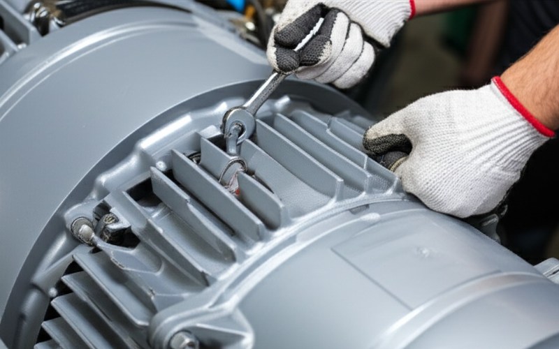
Buenas prácticas para la medición del espesor del recubrimiento en el laminado
1. Definir el espesor deseado
¿Necesitas el espesor del recubrimiento por cada cara? ¿La contribución total del recubrimiento a la altura de la pila? ¿El espesor local mínimo tras el troquelado? ¿El espesor medio del recubrimiento en la chapa de entrada?
Se trata de cuestiones diferentes. Una especificación imprecisa como “comprobar el espesor del recubrimiento” da lugar a datos de inspección de poca calidad. El operario podría medir el centro. Al cliente podría interesarle el borde. La pila podría presentar fallos en otro lugar.
Una instrucción más adecuada sería la siguiente:
“Mida el espesor del recubrimiento en las láminas sueltas antes de apilarlas, en los puntos indicados, a una distancia mínima de 5 mm de los bordes cortados, salvo que se especifique una inspección de los bordes. Indique el valor medio, el mínimo, el máximo, el rango, el principio de medición, la referencia de calibración y la cantidad de muestras”.”
No es nada sofisticado. Pero es más difícil malinterpretarlo.
2. Calibrar sobre el sustrato de laminación real
La calibración debe ajustarse lo máximo posible a las condiciones reales de trabajo:
del mismo tipo de acero eléctrico o con un comportamiento magnético equivalente
el mismo rango de espesor de chapa
acabado superficial similar
la misma familia de recubrimientos
el mismo lado de medición
el mismo rango de espesor previsto
En el caso de los recubrimientos finos, una pequeña desviación se convierte en un gran error. Unos pocos micrómetros pueden determinar si un lote resulta aceptable o no. La calibración de fábrica no es suficiente cuando el sustrato es magnético y la tolerancia es muy ajustada.
Utiliza láminas de referencia o muestras conocidas, pero comprueba que queden bien planas. El polvo, la grasa, las arrugas y la inclinación de la sonda pueden generar datos erróneos que, a simple vista, parecen correctos.
3. Mide antes de apilar
Apilar cosas oculta las pruebas.
Una vez que las láminas se han comprimido, entrelazado, soldado, adherido o barnizado, el espesor del recubrimiento se ve afectado por el contacto mecánico, los huecos de aire, el contacto con rebabas y la presión de montaje. El medidor no puede distinguir todos esos factores desde el exterior.
Los puntos de inspección más útiles suelen ser:
banda o chapa recubierta entrante
laminaciones sueltas tras el punzonado
muestras de control del mismo lote de recubrimiento
piezas antes de la exposición al calor
piezas tras la exposición al calor, si el proceso pudiera alterar el recubrimiento
Si más adelante surge una reclamación por parte de un cliente, las muestras conservadas resultan muy útiles. Te proporcionan un elemento cuantificable que no ha quedado oculto en el interior del núcleo.
4. Utiliza un mapa de medidas fijas
Las comprobaciones aleatorias dan lugar a una confianza aleatoria.
Crea un mapa. Utiliza siempre los mismos puntos. Incluye las regiones centrales, las regiones periféricas y las zonas de riesgo conocidas. Si es necesario medir los bordes, hazlo por separado de la medición normal de la superficie, ya que el comportamiento de la lectura cerca de los bordes puede variar.
Un mapa de inspección sencillo puede incluir:
tres lecturas de la zona central
tres lecturas de la zona exterior
dos lecturas cerca de zonas de alto tráfico
lecturas separadas en ambos lados si ambos lados están recubiertos
lecturas opcionales de la zona periférica mediante un método validado para la zona periférica
No hay que mezclar todos estos datos en una media sin tener en cuenta el contexto. Los datos de la zona periférica y los de superficie abierta responden a preguntas diferentes.
5. Indica la variación, no solo la media
El grosor medio puede ocultar el problema.
Un recubrimiento con varios puntos delgados cerca de las rebabas puede seguir presentando un valor medio aceptable. Un recubrimiento demasiado grueso en zonas de bajo riesgo puede perjudicar el factor de apilamiento sin mejorar el aislamiento donde realmente importa.
Indica, como mínimo:
número de lecturas
espesor medio
valor mínimo
valor máximo
rango o desviación estándar
principio de medición
tipo de sonda o tamaño de la sonda
método de calibración
condición parcial
mapa de mediciones
El valor mínimo suele ser lo primero que miran los ingenieros. La media no es inútil, pero no basta.
Solución de problemas relacionados con las lecturas de los medidores de corrientes parásitas en laminaciones
Síntoma
Causa probable
Qué hay que comprobar primero
Mejores medidas correctivas
Las lecturas se van sucediendo a lo largo del día
Temperatura, desgaste de la sonda, desviación de la calibración, presión ejercida por el operador
Vuelve a comprobar las muestras de cero y de referencia
Añadir comprobaciones de verificación programadas
Los valores son elevados cerca de los bordes
Efecto de borde, rebabas, la sonda no está bien apoyada
Compara por separado las lecturas de los extremos y del centro
Utilizar un retroceso de borde definido o una microsonda validada
Los valores son inferiores a lo previsto
Recubrimiento demasiado fino, configuración incorrecta del sustrato, metal al descubierto, recubrimiento dañado
Compáralo con una muestra recubierta conocida
Confirmar mediante una sección transversal o una probeta de control
Las lecturas se dispersan en torno a un mismo punto
Inclinación de la sonda, rugosidad, suciedad, contacto inestable
Limpia la superficie y utiliza un soporte para sondas
Añadir una guía de fijación o de contacto
En una de las caras se lee algo diferente
¿Se trata de un verdadero desequilibrio en el recubrimiento o del efecto de la dirección del proceso?
Mide ambos lados con la misma configuración
Realizar un seguimiento de los datos específicos de cada lado
Buen grosor, pero mal aislamiento
Grietas, poros, contaminación conductora, cortocircuitos por rebabas
Realizar una prueba de aislamiento superficial o de resistencia interlaminar
Considera el grosor y el aislamiento como controles independientes
El factor de apilamiento ha cambiado, pero el grosor parece normal
Compresión, distribución del recubrimiento, altura de las rebabas, planitud de la laminación
Compara la altura de la pila y las lecturas de las piezas sueltas
Añadir comprobaciones de rebabas y planitud
El espesor del recubrimiento no es lo mismo que el rendimiento del aislamiento
No se trata de una distinción menor.
Un recubrimiento puede ser grueso y presentar grietas. Puede ser fino y continuo. Puede tener buen aspecto en el centro y fallar cerca del borde de una ranura. El espesor ayuda a explicar el comportamiento del aislamiento, pero no lo demuestra.
En el caso de las láminas de acero eléctrico, la medición del espesor debe combinarse con ensayos relacionados con el aislamiento cuando la aplicación así lo requiera. La resistencia de aislamiento superficial, la resistencia interlaminar, el comportamiento ante la ruptura dieléctrica y las comprobaciones posteriores al proceso pueden revelar problemas que un medidor de espesor no detectaría.
El grosor responde a una pregunta: ¿Qué cantidad de recubrimiento parece haber?
Las pruebas eléctricas plantean otra cuestión: ¿Sigue la superficie laminada actuando como aislante en determinadas condiciones?
Ambas cuestiones deben formar parte de un plan de calidad riguroso.
Cómo elegir el calibre adecuado para los trabajos de laminación
Empieza por el sistema de materiales. No por el nombre del producto. Ni por la resolución de la pantalla.
Hazte estas preguntas antes de elegir un manómetro:
¿El sustrato es acero eléctrico magnético?
¿El recubrimiento es no conductor, semiconductivo o conductor?
¿Qué rango de espesores hay que medir?
¿El recubrimiento está en un lado o en ambos?
¿Es la pieza lo suficientemente plana como para que el contacto de la sonda sea estable?
¿Es necesario realizar mediciones cerca de ranuras, bordes o rebabas?
¿Se tomarán las lecturas antes o después del apilado?
¿Qué método de referencia se utilizará para validar el medidor?
¿La inspección requiere datos sobre el espesor, datos sobre el aislamiento o ambos?
En el caso de la mayoría de los recubrimientos no conductores aplicados a laminados magnéticos, lo primero que hay que tener en cuenta es la inducción magnética. Los métodos de corrientes parásitas pueden ser válidos, pero es necesario comprobarlos en la pieza real. Si el recubrimiento es conductor o la geometría es compleja, no se debe dar por sentado que ninguno de los dos métodos funcione sin realizar pruebas de correlación.
Flujo de trabajo recomendado para las inspecciones
Utiliza este flujo de trabajo para el control de la producción:
Crear un mapa de mediciones Define los puntos, los retrasos de los bordes, los lados y el número de muestras.
Preparar muestras de calibración reales Utiliza un sustrato sin recubrimiento y referencias conocidas que coincidan con el material de laminación.
Comprobar la repetibilidad del manómetro Realiza varias lecturas en el mismo punto antes de medir las piezas de producción.
Medir las laminaciones sueltas Evita basarte en las superficies acabadas de las pilas, a menos que esa sea la única opción disponible.
Distinguir las zonas normales de las zonas de riesgo Mantén los datos relativos a los bordes, las rebabas y las zonas de ranuras separados de las lecturas de las superficies abiertas.
Mínimo histórico y rango de fluctuación No indiques únicamente la media.
Comprueba los datos cuando los resultados sean importantes Utilice el cálculo basado en la sección transversal y la masa, los ensayos de aislamiento superficial o los ensayos de resistencia interlaminar cuando el resultado influya en la aceptación, el rechazo o las reclamaciones de los clientes.
PREGUNTAS FRECUENTES
¿Pueden los medidores de corrientes de Foucault medir el espesor del recubrimiento en las láminas?
Sí, pero solo cuando el medidor, la sonda, el sustrato, el recubrimiento y la calibración sean adecuados. Los medidores de recubrimiento por corrientes de Foucault estándar suelen funcionar mejor en sustratos conductores no magnéticos. Las láminas de acero eléctrico son magnéticas, por lo que el método debe validarse cuidadosamente.
¿Es la inducción magnética mejor que el método de corrientes parásitas para las láminas de acero eléctrico?
En el caso de los recubrimientos no conductores sobre acero eléctrico magnético, la inducción magnética suele ser el método más directo. Las técnicas de corrientes parásitas pueden seguir siendo válidas en determinadas configuraciones especializadas, pero no debe darse por sentado que son precisas sin realizar pruebas de correlación.
¿Por qué las lecturas del espesor del recubrimiento son inestables cerca de los bordes de la laminación?
Los bordes cortados pueden alterar el campo de la sonda. También pueden presentar rebabas, rebordes, acero al descubierto, recubrimiento agrietado o deformaciones locales. Estos efectos pueden alterar la lectura, incluso cuando el recubrimiento alejado del borde se encuentra en buen estado.
¿Puedo medir el espesor del recubrimiento una vez apiladas las láminas?
Se pueden medir las superficies exteriores accesibles, pero eso no demuestra el espesor del recubrimiento ni el estado del aislamiento entre las láminas internas. Para un control real del recubrimiento, mide las láminas sueltas o las muestras de referencia antes de apilarlas.
¿Un recubrimiento más grueso mejora siempre el aislamiento de la laminación?
No. Un recubrimiento más grueso puede mejorar la separación en algunos casos, pero puede reducir el factor de apilamiento y es posible que no solucione los problemas de grietas, cortocircuitos por rebabas o contaminación. El objetivo debe ser un rango de espesor controlado, respaldado por datos sobre el rendimiento del aislamiento.
¿Cuál es la mejor forma de validar un medidor para recubrimientos de laminación?
Mida muestras de referencia conocidas fabricadas con el mismo sustrato y sistema de recubrimiento. A continuación, compare las lecturas del medidor con un método de referencia fiable, como la medición de la sección transversal, el cálculo del recubrimiento basado en la masa o una prueba de aislamiento eléctrico acordada.
¿Por qué puede superarse el requisito de espesor del recubrimiento mientras que el de aislamiento superficial no se cumple?
El espesor no garantiza la continuidad. Las grietas, los poros, los residuos conductores, los bordes dañados o las rebabas pueden crear vías eléctricas incluso cuando el espesor medio del recubrimiento parece aceptable.
¿Cuántas mediciones hay que realizar por cada laminado?
No existe una cifra universal. Realiza suficientes mediciones para detectar las variaciones en toda la pieza. Es mejor un mapa fijo con puntos centrales, exteriores y de zona de riesgo que unas pocas mediciones aleatorias.
¿Qué debe incluirse en un informe de inspección del espesor del recubrimiento?
Incluye el número de muestras, los puntos de medición, el valor medio, el mínimo, el máximo, el rango, el principio de medición, el tamaño de la sonda, el método de calibración, el tipo de sustrato, la cara del recubrimiento y el estado de la pieza. Si se incluyen lecturas de los bordes, indícalas por separado.
Conclusión principal
La medición del espesor del recubrimiento en las láminas no consiste simplemente en tocar el acero con una sonda y anotar un número.
El sustrato puede ser magnético. El recubrimiento puede ser muy fino. El borde puede estar dañado. La pila de capas puede ocultar los puntos de contacto reales. El medidor puede ser preciso, pero no válido para la pieza.
Utiliza medidores de corrientes de Foucault cuando sea adecuado. Recurre a la inducción magnética cuando la combinación de materiales lo requiera. Valida el método con muestras reales de laminados. Mantén separados los datos de los bordes. Combina las comprobaciones de espesor con las pruebas de aislamiento cuando el rendimiento sea determinante.
Una pila de laminación suele dar señales de advertencia antes de que se produzca un fallo más grave. Una mejor medición del recubrimiento te ayuda a detectar esas señales mientras las piezas aún se pueden medir.
Cheney es un ingeniero de aplicaciones sénior de Sino con una gran pasión por la fabricación de precisión. Es Ingeniero Mecánico y posee una amplia experiencia práctica en fabricación. En Sino, Cheney se centra en optimizar los procesos de fabricación de pilas de laminación y en aplicar técnicas innovadoras para conseguir productos de pilas de laminación de alta calidad.
Folleto de nuevos productos
Introduzca su dirección de correo electrónico y le enviaremos el folleto más reciente.
Deje que las pilas de laminación de Sino potencien su proyecto.
Para agilizar su proyecto, puede etiquetar las pilas de laminación con detalles como tolerancia, material, acabado superficial, si se requiere o no aislamiento oxidado, cantidady mucho más.