Let Sino's Lamination Stacks Empower Your Project!
To speed up your project, you can label Lamination Stacks with details such as tolerance, material, surface finish, whether or not oxidized insulation is required, quantity, and more.
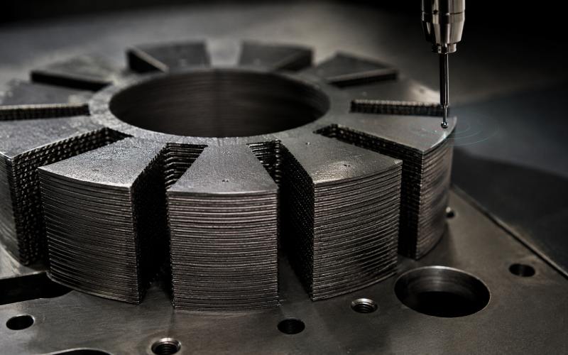
Eddy-current gauges can measure coating thickness on laminations quickly, but they are not automatically the right tool for every lamination job. The main issue is the substrate. Many motor, generator, and transformer laminations are made from magnetic electrical steel, while standard eddy-current coating gauges are often designed for non-conductive coatings on non-magnetic conductive metals.
For magnetic electrical steel, magnetic induction is often the more direct coating-thickness principle. Eddy-current methods may still work in certain setups, especially with suitable probes and validation, but they must not be treated as plug-and-play.
The practical answer is simple enough: choose the measurement principle based on the substrate, validate it on the exact lamination material, measure before stacking whenever possible, and never confuse coating thickness with insulation performance.
That is the clean version. The shop-floor version is messier.
A lamination coating is thin. Sometimes only a few micrometres. That makes it easy to underestimate.
The coating helps separate metal sheets in a stack. This separation reduces interlaminar current paths, supports electrical insulation, limits corrosion, and affects stack build. If the coating is too thin, local shorts can occur between laminations. If it is too thick, the stack factor may drop because less of the stack height is useful magnetic steel.
There is also the awkward middle case: the coating looks acceptable on average, but it is weak near punched edges, burrs, slots, or pressure zones. That is where failures often start. Not politely in the center of a flat test coupon. Usually at the part of the lamination nobody measured.
An eddy-current gauge uses a probe coil carrying alternating current. The probe creates an electromagnetic field. When the probe approaches a conductive base material, that field induces small circulating currents in the metal.
The coating changes the distance between the probe and the conductive substrate. This distance change alters the probe signal. The gauge converts that signal into coating thickness.
That explanation fits many simple cases: a non-conductive coating over a non-magnetic conductive base.
Laminations are not always that simple.
Electrical steel is conductive and magnetic. The magnetic behavior affects the probe signal, sometimes strongly. A gauge may read coating lift-off, substrate permeability, sheet thickness effects, surface roughness, or a mix of all four. The number on the display may look stable. It can still be measuring the wrong thing.
This is the part many coating-thickness guides avoid, but it matters.
For lamination coatings, the measurement principle should be selected from the material pair: coating plus substrate.
| Substrate and coating condition | Usually suitable method | Why | Main warning |
|---|---|---|---|
| Non-conductive coating on non-magnetic conductive metal | Eddy-current | The probe senses lift-off from the conductive base | Not the usual case for electrical steel laminations |
| Non-conductive coating on magnetic steel | Magnetic induction | The probe senses distance from a ferromagnetic base | Best validated with real lamination samples |
| Very thin coating on magnetic electrical steel | Magnetic induction or validated specialized eddy-current setup | Small thickness changes are sensitive to calibration error | Do not rely on factory calibration alone |
| Conductive or semi-conductive coating | Specialized method or reference verification | Standard assumptions may fail | Confirm with cross-section, mass-based, or electrical test data |
| Finished lamination stack | Limited surface measurement only | Internal coating condition is hidden | Outer readings do not prove interlaminar insulation |
A common mistake is asking, “Can an eddy-current gauge measure this?”
The better question is: Which electromagnetic response is the gauge actually using, and has that response been proven on this coated electrical steel?
Amplitude-sensitive eddy-current gauges can be affected by permeability changes in magnetic substrates. Phase-sensitive or dual-method instruments may separate some effects, but only within their designed range. Magnetic induction is often the safer starting point for non-magnetic coatings on ferromagnetic laminations.
Still, do not choose by theory alone. Validate.
A flat, unpunched coupon is easy. A punched lamination is less friendly. A finished stack is worse.
Laminations bring several measurement problems at once:
A gauge reading on the exposed outside of a stack does not tell you what happened between internal sheets. It only tells you something about the accessible surface. Maybe useful. Maybe not enough.
For process control, measure loose laminations, incoming coated strip, punched samples, or witness coupons. If the part is already stacked, use the reading carefully. Do not pretend it sees through the stack.
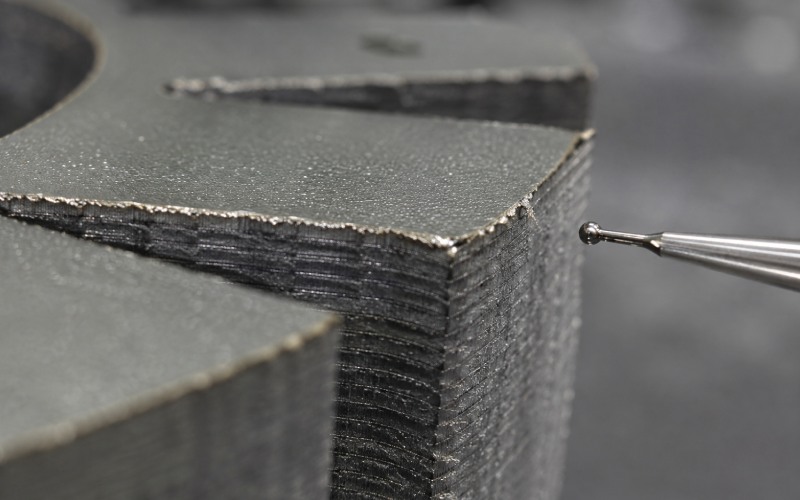
Do you need coating thickness per side? Total coating contribution to stack height? Minimum local thickness after punching? Average coating on incoming sheet?
These are different questions. A vague specification like “check coating thickness” creates poor inspection data. The operator may measure the center. The customer may care about the edge. The stack may fail somewhere else.
A better instruction looks like this:
“Measure coating thickness on loose laminations before stacking, at mapped locations at least 5 mm from cut edges unless edge inspection is specified. Report average, minimum, maximum, range, measurement principle, calibration reference, and sample quantity.”
Not fancy. Harder to misread.
Calibration should match the real job as closely as possible:
For thin coatings, a small offset becomes a large error. A few micrometres can decide whether a batch looks acceptable or not. Factory calibration is not enough when the substrate is magnetic and the tolerance is tight.
Use reference foils or known samples, but check that they sit flat. Dust, oil, wrinkles, and probe tilt can produce clean-looking bad data.
Stacking hides evidence.
Once laminations are compressed, interlocked, welded, bonded, or varnished, coating thickness becomes mixed with mechanical contact, air gaps, burr contact, and assembly pressure. The gauge cannot separate all of that from the outside.
The most useful inspection points are usually:
If a customer dispute happens later, retained samples are valuable. They give you something measurable that has not been buried inside the core.
Random probing gives random confidence.
Create a map. Use the same points each time. Include center regions, outer regions, and known risk zones. If edge measurement is required, separate it from normal surface measurement because the reading behavior near edges may differ.
A simple inspection map may include:
Do not mix all of these into one average without context. Edge-zone data and open-surface data answer different questions.
Average thickness can hide the problem.
A coating with several thin points near burrs may still show a decent mean value. A coating that is too thick in low-risk areas may hurt stack factor without improving insulation where it matters.
Report at least:
The minimum value is often the number engineers look at first. The average is not useless. It is just not enough.
| Symptom | Likely cause | What to check first | Better corrective action |
|---|---|---|---|
| Readings drift across the day | Temperature, probe wear, calibration shift, operator pressure | Recheck zero and reference samples | Add scheduled verification checks |
| Values are high near edges | Edge effect, burrs, probe not seated flat | Compare edge and center readings separately | Use defined edge setback or validated micro-probe |
| Values are lower than expected | Thin coating, wrong substrate setting, exposed metal, damaged coating | Check against a known coated sample | Confirm with cross-section or witness coupon |
| Readings scatter on the same point | Probe tilt, roughness, dirt, unstable contact | Clean surface and use a probe stand | Add fixture or contact guide |
| One side reads differently | True coating imbalance or process direction effect | Measure both sides with same setup | Track side-specific data |
| Good thickness but poor insulation | Cracks, pinholes, conductive contamination, burr shorts | Run surface insulation or interlaminar resistance test | Treat thickness and insulation as separate controls |
| Stack factor changed but thickness looks normal | Compression, coating distribution, burr height, lamination flatness | Compare stack height and loose-part readings | Add burr and flatness checks |
This is not a small distinction.
A coating can be thick and cracked. It can be thin and continuous. It can look fine in the center and fail near a slot edge. Thickness helps explain insulation behavior, but it does not prove it.
For electrical steel laminations, thickness measurement should be paired with insulation-related testing when the application requires it. Surface insulation resistance, interlaminar resistance, breakdown behavior, and post-process checks can reveal problems that a thickness gauge will miss.
Thickness answers one question: How much coating appears to be present?
Electrical testing asks another: Does the lamination surface still insulate under defined conditions?
Both questions belong in a serious quality plan.

Start with the material system. Not the product name. Not the display resolution.
Ask these questions before selecting a gauge:
For most non-conductive coatings on magnetic laminations, magnetic induction deserves first consideration. Eddy-current methods may be valid, but they need proof on the actual part. If the coating is conductive or the geometry is tight, do not assume either method works without correlation testing.
Use this workflow for production control:
Yes, but only when the gauge, probe, substrate, coating, and calibration are suitable. Standard eddy-current coating gauges are usually most straightforward on non-magnetic conductive substrates. Electrical steel laminations are magnetic, so the method must be validated carefully.
For non-conductive coatings on magnetic electrical steel, magnetic induction is often the more direct method. Eddy-current techniques may still work in certain specialized setups, but they should not be assumed accurate without correlation testing.
Cut edges can disturb the probe field. They may also contain burrs, rollover, exposed steel, cracked coating, or local deformation. These effects can change the reading even when the coating away from the edge is stable.
You can measure accessible outer surfaces, but that does not prove the coating thickness or insulation condition between internal sheets. For real coating control, measure loose laminations or witness samples before stacking.
No. Thicker coating may improve separation in some cases, but it can reduce stack factor and may not fix cracks, burr shorts, or contamination. The target should be a controlled thickness range supported by insulation performance data.
Measure known reference samples made from the same substrate and coating system. Then compare gauge readings with a trusted reference method, such as cross-section measurement, mass-based coating calculation, or an agreed electrical insulation test.
Thickness does not prove continuity. Cracks, pinholes, conductive residue, damaged edges, or burrs can create electrical paths even when average coating thickness looks acceptable.
There is no universal number. Use enough readings to capture variation across the part. A fixed map with center, outer, and risk-zone points is better than a few random readings.
Include sample count, measurement locations, average, minimum, maximum, range, gauge principle, probe size, calibration method, substrate type, coating side, and part condition. If edge readings are included, label them separately.
Coating thickness measurement on laminations is not just touching a probe to steel and recording a number.
The substrate may be magnetic. The coating may be very thin. The edge may be damaged. The stack may hide the real contact points. The gauge may be precise but not valid for the part.
Use eddy-current gauges where they fit. Use magnetic induction when the material pair calls for it. Validate the method on real lamination samples. Keep edge data separate. Pair thickness checks with insulation testing when performance matters.
A lamination stack usually gives warning signs before it creates a larger failure. Better coating measurement helps you catch those signs while the parts are still measurable.








 English
  German
  Spanish
  French
  Italian