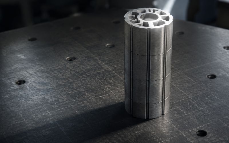
Let Sino's Lamination Stacks Empower Your Project!
To speed up your project, you can label Lamination Stacks with details such as tolerance, material, surface finish, whether or not oxidized insulation is required, quantity, and more.
Lamination stack height is not just a total thickness number. In real production, a stack can meet height tolerance and still fail during assembly because of tilt, poor squareness, burr buildup, uneven compression, or the wrong datum.
A practical QC routine should answer four questions:
For stator cores, rotor cores, transformer cores, and precision lamination stacks, the best inspection plan combines multi-point stack height measurement, GD&T-style perpendicularity thinking, and clear process-stage control.
A lamination stack may pass a single height check and still create assembly problems.
That usually happens because the measurement is too simple.
One center reading does not show side-to-side tilt. One end-face reading does not show burr buildup on the opposite side. A free-state reading does not always predict what happens after clamping, bonding, welding, interlocking, or final assembly.
The final product does not react to the average stack height. It reacts to contact points, compression behavior, and alignment.
That is why stack height and squareness should be treated as related but separate QC controls.
These terms are often used loosely on the shop floor. That causes inspection arguments.
| Measurement term | What it controls | Typical QC question | Common mistake |
|---|---|---|---|
| Stack height | Total build height of the lamination stack | Is the stack too tall or too short? | Taking only one reading |
| Flatness | Surface variation of one face | Is the end face locally high, low, crowned, or warped? | Assuming flatness proves assembly alignment |
| Parallelism | Consistency between two opposite faces | Are the top and bottom faces evenly spaced? | Missing bore or OD relationship |
| Squareness | Practical 90° relationship between features | Does the stack stand correctly against the functional datum? | Not naming the datum |
| Perpendicularity | GD&T orientation control relative to a datum | Is this surface, axis, or center plane within the allowed 90° tolerance zone? | Treating it as a simple angle check |
In GD&T terms, perpendicularity controls whether a surface, axis, or center plane is oriented at 90° to a defined datum within a tolerance zone. That matters because “square” only has meaning after the datum is clear.
Before measuring, define the datum.
Not later. Not after a reject. Before.
A useful rule is simple:
Measure from the feature that controls assembly function.
For example:
| Lamination stack type | Functional concern | Better datum choice |
|---|---|---|
| Rotor lamination stack | Concentric rotation and shaft fit | Bore or mandrel axis |
| Stator lamination stack | Housing fit and air-gap control | OD, bore, or mounting face |
| Transformer core stack | Pack height and face contact | Clamping face or base face |
| Segmented stack | Segment seating and angular fit | Fixture nest or locating feature |
| Bonded or welded stack | Post-process distortion | Same datum used in final assembly |
The wrong datum can make a bad stack look good. It can also make a good stack look bad. Both are expensive.
A strong height routine has three parts: condition, point map, and record format.
Do not mix free-state and loaded readings in the same data trend.
Use one of these labels:
Loaded height is often more useful when the stack is compressed in the final product. Free-state height is still useful for setup checks, lamination count errors, and early process drift.
Dust, burr fragments, oil lumps, coating debris, and loose chips can create false height. Clean the reference plate, fixture, and stack face before inspection.
Do not over-clean. The goal is not to improve the part. The goal is to remove false spacers.
A one-point reading is weak data.
For round stator or rotor stacks, start with:
For rectangular or segmented stacks, measure:
The average height may look fine while one side is high.
Record:
| Data field | Why it matters |
|---|---|
| Maximum height | Shows the highest assembly contact risk |
| Minimum height | Shows low-side compression or missing material risk |
| Height range | Reveals tilt, crown, or uneven seating |
| Average height | Useful for trend monitoring |
| Measurement points | Makes the data repeatable |
| Load condition | Prevents false comparison |
| Fixture ID | Helps detect worn or unstable tooling |
A stack that is high everywhere usually points to count, material thickness, coating, or compression. A stack that is high on one side points to burr direction, seating error, fixture tilt, or local debris.
That distinction saves time.
Squareness should be checked against the datum that matters in assembly.
This is useful for rotor stacks and precision stacks that locate from an internal bore.
Procedure:
This method checks whether the end face is square to the bore axis. It is often more meaningful than checking the stack only against a surface plate.
This is useful when the stack must stand correctly in a housing, clamp, or assembly nest.
Procedure:
Avoid damaged edges. Measure the functional side surface, not a burr peak.
A height map can show probable squareness issues.
Example:
| Point | Height trend | Possible meaning |
|---|---|---|
| 0° high, 180° low | Side-to-side tilt | Burr stack-up, fixture tilt, uneven seating |
| All points high | Total height issue | Count, coating, material thickness, low compression |
| One local point high | Local defect | Debris, dent, weld pull, interlock distortion |
| Center high | Crown or trapped layer | Pressing, bonding, or layer seating issue |
This is not a full perpendicularity check, but it tells QC where to look next.
Manual inspection is useful. It is also limited.
The right method depends on production volume, tolerance risk, and the cost of failure.
| Inspection method | Best for | Strength | Limitation |
|---|---|---|---|
| Height gauge and surface plate | Prototype, low-volume, incoming checks | Simple and low cost | Operator influence, slower data capture |
| Dial indicator with fixture | Process checks and first-off approval | Good repeatability if fixture is stable | Limited point coverage |
| Functional mandrel inspection | Rotor stacks and bore-based datums | Checks assembly-relevant alignment | Requires accurate mandrel control |
| CMM inspection | Detailed dimensional validation | Strong datum control and traceable data | Slower for high-volume production |
| Laser or non-contact scanning | High point-density checks | Finds shape patterns quickly | Needs clear method and correlation to function |
| Automated multi-point station | High-volume stator and rotor production | Fast, repeatable, data-rich | Requires upfront fixture and method design |
A practical approach is to use manual methods for setup and diagnosis, then move to fixture-based or automated inspection when volume, tolerance, or defect cost justifies it.
| Production stage | Inspection focus | Recommended check | Purpose |
|---|---|---|---|
| Incoming laminations | Thickness, burr direction, visual defects | Sampling by lot or coil | Prevent repeated layer error |
| First stack after setup | Count, seating, free height | Multi-point height map | Catch setup mistakes early |
| Pre-joining stack | Height under defined condition | Loaded or fixture-seated check | Confirm stack behavior before value is added |
| Post-joining stack | Distortion, tilt, local high points | Height map plus squareness check | Detect weld, bond, rivet, or interlock effects |
| Final stack | Functional fit | Datum-based height and perpendicularity-style check | Confirm assembly readiness |
| Gauge audit | Measurement stability | Master check and fixture review | Prevent false process drift |
The inspection plan should follow the risk. Do not add checks just to look thorough. Add checks where the process can actually move.
| Problem found | Likely cause | First action |
|---|---|---|
| Stack height too high at all points | Too many laminations, thick material, coating buildup, low compression | Verify count, material, and load |
| Stack height too low | Missing lamination, over-compression, wrong material thickness | Check count and press condition |
| One side high | Burr direction, tilted fixture, uneven seating | Rotate and remeasure |
| Local high point | Dirt, chip, dent, weld pull, interlock deformation | Clean, inspect edge, isolate location |
| Good height but poor squareness | Datum mismatch or tilted face | Recheck against functional datum |
| Good pre-join, bad post-join | Joining distortion | Review clamp force and sequence |
| Poor repeatability | Operator method, fixture wear, unclear point map | Run repeatability check |
| Assembly failure despite passed height | Average height masked tilt or local contact | Add range and squareness controls |
Most stack issues leave a pattern. The goal is to read the pattern before adjusting the process.
Use this checklist before accepting stack height or squareness data.
The last point matters. Deleted failures hide the process.
Manual stack measurement works well for small batches, trial builds, and troubleshooting. It becomes weak when the process needs speed, traceability, and low operator variation.
Consider a more controlled inspection method when:
At that point, the question is not “Can a person measure this?” The better question is, “Can this method catch the defect before it reaches assembly?”
Lamination stack height is the total measured build height of stacked laminations between two reference faces. It may be measured free-state, seated, clamped, or under a defined load.
Use a stable datum, define the stack condition, then measure multiple points across the stack face. Record maximum height, minimum height, average height, range, point locations, and measurement load.
If the stack is compressed in final assembly, loaded height is usually more useful than free-state height. Free-state height is still helpful for setup checks and early defect detection.
Squareness is the practical 90° relationship between stack features, such as the end face and bore axis, or the side wall and datum face. In GD&T language, this is closely related to perpendicularity.
Because one height reading can hide tilt, crown, burr buildup, local high points, or datum mismatch. Assembly usually reacts to the first contact point, not the average height.
For round stacks, start with four points around the outer region and add points near functional or high-risk areas. For larger or tighter-tolerance stacks, use a denser point map.
Common causes include burr stacking, uneven seating, worn fixtures, joining distortion, debris between layers, inconsistent compression, and inspection from the wrong datum.
Not always. A CMM is useful for detailed validation and datum-controlled checks. For production monitoring, a dedicated fixture or automated multi-point station may be faster and more practical.
Use first-off validation, loaded height checks, post-join squareness checks, fixture audits, and automated or semi-automated data capture where repeatability is critical.
Control burr direction, lamination count, seating load, fixture condition, joining sequence, and measurement datum. Then track height range and squareness trend, not only average height.
Reliable lamination stack QC is not built around one height number.
It is built around datum control, stack condition, multi-point measurement, and functional squareness. A good routine shows whether the stack is too tall, too short, tilted, locally high, or changing after joining.
That is the difference between inspection data that only fills a report and inspection data that prevents assembly problems.