Let Sino's Lamination Stacks Empower Your Project!
To speed up your project, you can label Lamination Stacks with details such as tolerance, material, surface finish, whether or not oxidized insulation is required, quantity, and more.
For stator and rotor lamination stacks, the strongest inspection plan is rarely CMM vs vision vs gauges. It is usually CMM plus vision plus gauges, with each method assigned to the right feature and the right stage of production.
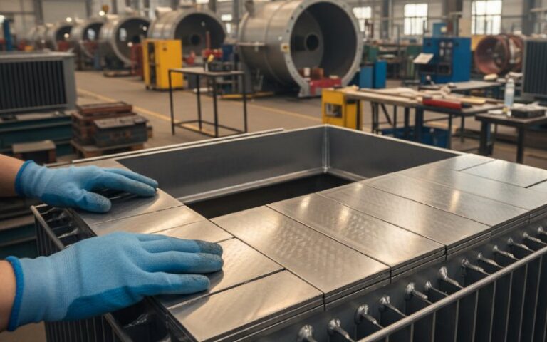
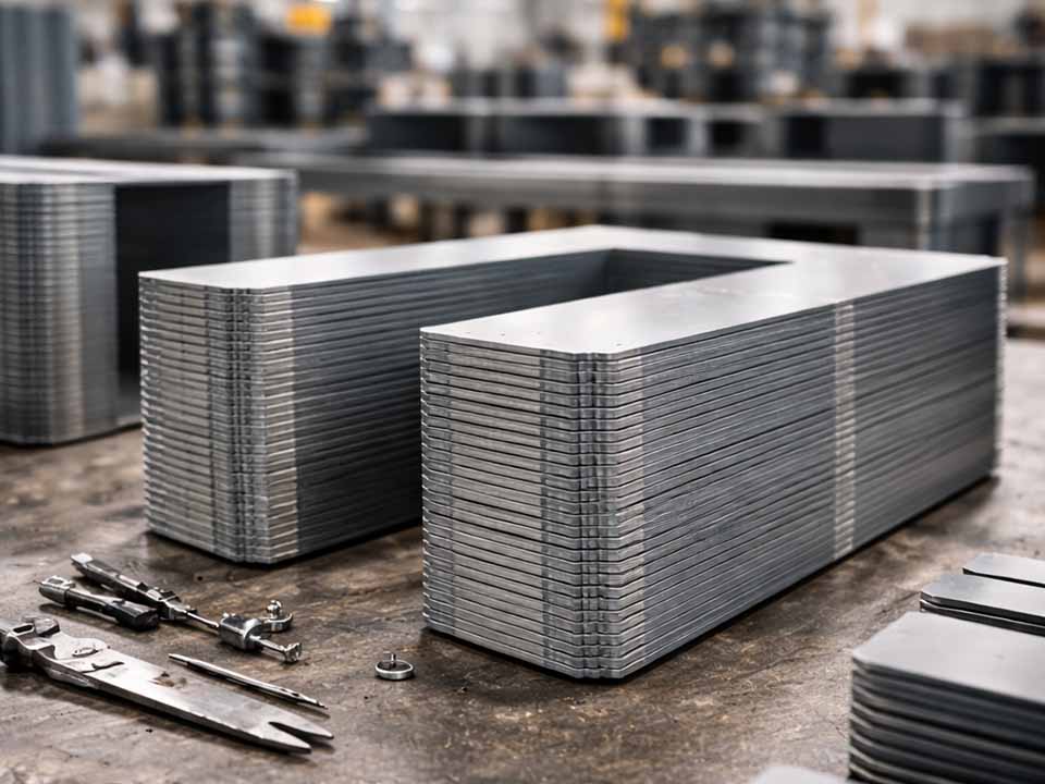
A lamination stack is not just a metal part with a height, bore, and outside diameter.
It is hundreds of thin electrical steel sheets behaving as one component. Mostly. Not perfectly.
That small detail matters. A stack can pass height inspection and still fail assembly because height does not reveal layer shift, burr buildup, face wave, skew error, or bore-to-OD relationship. A rotor can look acceptable on a simple OD check but still create air gap variation. A stator can pass basic slot width measurement and still create winding insertion problems.
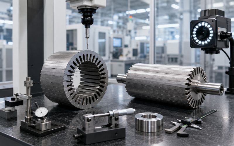
This is why stator stack dimensional inspection and rotor lamination inspection need more than one measurement method.
The inspection method should follow the failure mode:
A clean inspection plan starts there. Not with the machine.
| Inspection method | Best for | Weak point | Best production use | Output |
|---|---|---|---|---|
| CMM inspection | GD&T, datums, bore-to-OD concentricity, flatness, parallelism, position, runout studies | Slower; needs good fixturing and measurement strategy | First article inspection, PPAP, process validation, periodic audit | Actual measured values |
| Vision inspection | 2D profile, slots, teeth, magnet pockets, notches, layer offset, orientation, burr trend | Edge detection depends on lighting, focus, contrast, surface condition | High-speed in-process inspection, 100% checks where practical | Measured values or pass/fail |
| Functional gauges | Shaft fit, housing fit, magnet insertion, slot clearance, stack height go/no-go | Usually no full measurement data; gauge wear must be controlled | Operator checks, assembly checks, containment | Pass/fail |
| Hybrid inspection | Full lamination stack control plan | Needs correlation between systems | Mature EV motor and industrial motor production | Data plus function |
A CMM gives stronger dimensional evidence. Vision gives speed. Gauges give functional confidence.
None of them should be asked to do everything.
CMM inspection is the right choice when the feature has a datum relationship or when the measurement result must support quality documentation.
Use CMM for:
CMM inspection is especially useful when the drawing uses GD&T. Position, flatness, profile, perpendicularity, parallelism, and runout need a measurement strategy that respects the datum structure. CMMs are commonly evaluated through acceptance and reverification methods such as the ISO 10360 series, which covers coordinate measuring machine performance testing.
But CMM inspection can mislead if the lamination stack is not fixtured in the same condition as the real assembly.
A free-state stack may measure differently from a clamped stack. A welded stack may shift after heat input. A bonded stack may change after curing. A press-fit rotor core may not behave like the loose stack measured earlier.
So the CMM question is not just:
What is the dimension?
It is:
What is the dimension under the condition that matters?
For tight EV traction motor work, CMM is often used as the reference method for validation, correlation, and root-cause analysis. It does not always belong on every part, every minute. That would often be slow and expensive. It belongs where measurement depth matters.
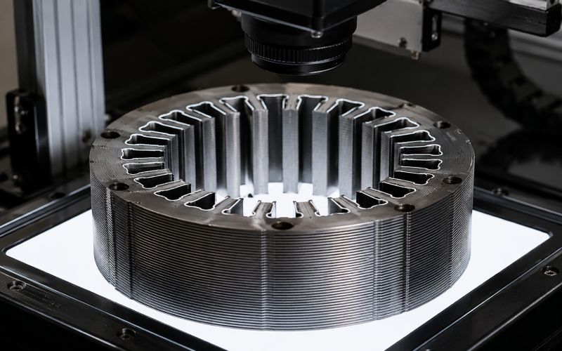
Vision inspection is strongest when the feature is visible, edge-based, and repeated many times.
That describes many lamination features.
Use vision inspection for:
A vision system measures by capturing images, detecting edges, and converting pixel data into dimensional results through calibration. The method depends heavily on lighting, optics, focus, part positioning, contrast, and edge detection rules; these factors are central to good practice in dimensional vision measurement.
This is where many inspection projects go wrong.
A camera does not measure the part directly. It measures the image of the part. That image can change because of oil, coating gloss, burr shadow, edge rollover, vibration, part tilt, or lighting drift.
For lamination stacks, vision inspection works best when the inspection plan defines:
Vision is usually the best choice for high-frequency checks. It can catch trends early: tooth width drift, slot shape movement, pocket edge shift, or wrong lamination orientation.
But vision is not always enough for 3D relationships. It may see the top face clearly and still miss internal stack behavior.
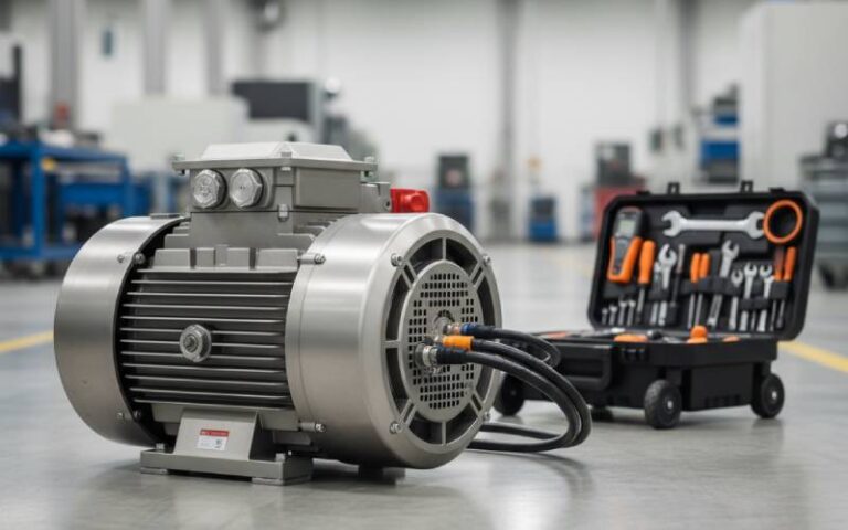
Gauges are not old-fashioned. Bad gauges are old-fashioned.
A good functional gauge answers a production question in the same language as assembly:
Use gauges for:
A gauge will not tell you the actual bore roundness or the exact pocket position. That is not its job.
Its job is to protect the line.
For example, a rotor core may have a magnet pocket that measures slightly different depending on edge detection or probe strategy. A magnet insertion gauge can reveal the actual assembly risk quickly. That does not replace CMM or vision. It adds a functional layer.
Gauges need control, though. Gauge wear, dirt, burr damage, thermal expansion, operator technique, and unclear go/no-go rules can all create false confidence. A gauge should be included in MSA. Gage R&R studies are used to separate measurement variation into repeatability and reproducibility components, helping determine whether the measurement system itself is adding too much variation.
| Feature or risk | Recommended primary method | Secondary method | Reason |
|---|---|---|---|
| Bore diameter | CMM or bore gauge | Functional plug gauge | Needs size data and fit confirmation |
| Bore-to-OD concentricity | CMM | Rotational gauge | Affects air gap and rotor/stator alignment |
| Stator slot width | Vision | Slot clearance gauge | Vision checks profile; gauge confirms function |
| Hairpin stator slot clearance | Functional gauge | Vision | Assembly behavior matters more than one width value |
| Rotor magnet pocket width | Vision or CMM | Magnet insertion gauge | Edge geometry and fit both matter |
| Magnet pocket position | CMM | Vision | Datum relationship is important |
| Stack height | Height gauge or fixture gauge | CMM audit | Fast check needed; audit confirms deeper issues |
| Face flatness | CMM | Seating fixture check | Height alone misses face wave |
| Layer offset | Vision | CMM audit | Visible-face check is fast |
| Skew angle | CMM or dedicated fixture | Vision | Depends on stack design |
| Burr trend | Vision | Manual audit | Contrast-based detection can be fast |
| Shaft fit | Functional gauge | CMM | Fit must be protected at the line |
This table is the core of the decision.
If the feature controls geometry, use CMM. If the feature controls visible shape at speed, use vision. If the feature controls assembly fit, use gauges.
Some features need all three.
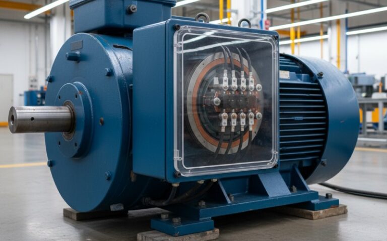
EV traction motors usually put more pressure on lamination inspection because air gap, efficiency, noise, magnet retention, and high-volume repeatability all matter at the same time.
For EV stator and rotor cores, pay attention to:
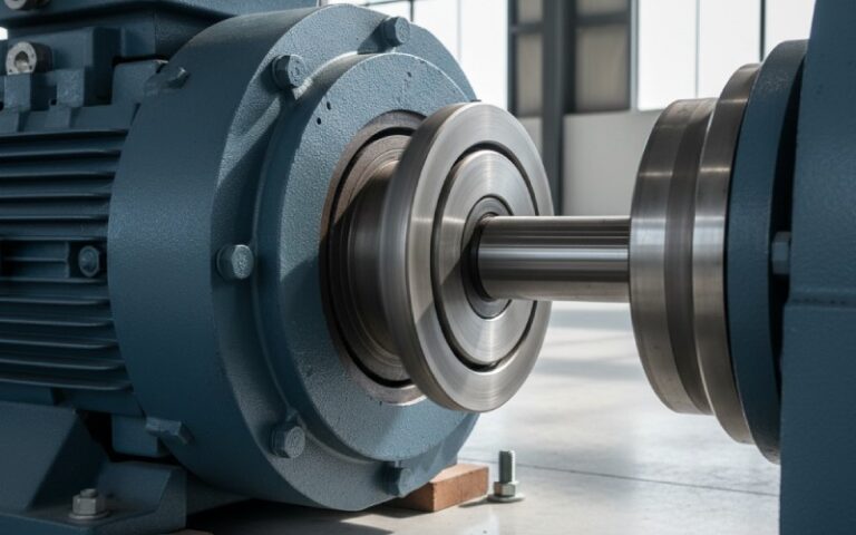
Air gap issues are rarely caused by one number. Bore geometry, OD geometry, concentricity, stack seating, housing fit, and rotor runout can all contribute.
CMM inspection should verify datum relationships. Functional checks should confirm the stack locates the same way it will locate in the motor.
Hairpin winding is less forgiving than loose wire winding. Slot opening, slot wall condition, insulation clearance, and layer shift can create insertion resistance.
Vision can check slot profile quickly. A slot gauge can confirm actual clearance. CMM can audit datum relationship and slot position.
Rotor magnet pockets need width, length, bridge geometry, and position control. A pocket that is acceptable in 2D may still cause insertion problems if burrs, stack offset, or local deformation are present.
Use vision for profile, CMM for position, and insertion gauges for function.
Once production is stable, inspection should move beyond pass/fail.
Use Cpk on critical features such as bore size, pocket width, slot width, stack height, or datum-related position when variable data is available. Process capability compares an in-control process with specification limits using capability indices.
If the feature is checked only by go/no-go gauge, you may protect assembly, but you will have less trend data. That is acceptable for some features. Not for all.
A strong lamination stack inspection plan usually has five layers.
Check individual lamination profile before stacking. Vision inspection is often the fastest method for slots, teeth, holes, notches, and pocket geometry.
Control the nest, pins, datum surfaces, press force, lamination orientation, burr direction, and stack seating. A good measurement system cannot fully rescue an unstable stacking process.
Check stack height, face condition, bore, OD, concentricity, and layer offset. Use CMM where datum relationships matter. Use vision for fast visible checks. Use gauges for line decisions.
If the stack is welded, bonded, riveted, cleated, or interlocked, measure after the joining process. Joining can change geometry.
Use functional gauges or assembly simulation fixtures for shaft fit, housing fit, magnet insertion, and winding clearance.
This is not overinspection. It is staged inspection. Each stage catches a different failure mode.
Stack height does not prove flatness, parallelism, seating, or layer alignment.
If the part moves, flexes, rocks, or sits on burrs, the CMM report may look precise while the result is not useful.
Vision measurement depends on image quality. If lighting changes, the edge can move. Then the measurement moves too.
A gauge that cannot repeat is not a control method. It is a sorting habit.
CMM, vision, and gauges should be tested on the same parts during launch. If they disagree, solve that early. Do not wait until production scrap starts.
For most stator and rotor lamination stack programs:
The best system is not the one with the most advanced equipment. It is the one that catches the right failure at the right point in the process.
If you are building or revising a stator/rotor lamination inspection plan, start with three documents:
From there, each feature can be assigned to CMM, vision, gauges, or a hybrid method.
For a practical review, prepare the lamination drawing, stack specification, datum scheme, critical-to-quality features, and known assembly problems. A metrology review can usually identify which checks should stay in the lab, which can move to automated vision, and which should become functional gauges on the production floor.
There is no single best method. CMM is best for traceable dimensional measurement and GD&T. Vision is best for fast profile and edge inspection. Gauges are best for functional fit checks. Most lamination stack programs need all three.
Vision inspection can replace selected CMM checks after correlation, especially for visible 2D features. It should not replace CMM for datum-heavy GD&T, deep 3D relationships, first article inspection, or process validation.
Yes, when the gauge is designed around the real assembly function and controlled through calibration and Gage R&R. Gauges are especially useful for shaft fit, magnet insertion, housing fit, and slot clearance.
Common stator stack checks include bore size, OD, slot width, tooth geometry, slot opening, bore-to-OD concentricity, stack height, flatness, parallelism, layer offset, and housing datum features.
Because the inspection may be checking the wrong condition. A stack can pass height but fail flatness. It can pass slot width but fail winding insertion. It can pass pocket width but fail magnet insertion due to burrs or layer shift.
Measure them in the condition that matches the functional requirement. If the stack is clamped in the motor, a loaded or seated inspection may be more useful than free-state measurement.
Correlate them during launch, after tooling changes, after fixture repair, after camera or lighting changes, after gauge repair, and whenever measurement results no longer match assembly behavior.
Cpk helps show whether a stable process can meet specification limits. It is useful for critical dimensions such as bore size, slot width, magnet pocket width, and stack height, but only if the measurement system is reliable.
Stop assigning inspection methods by habit. Assign them by failure mode. Use CMM for geometry, vision for fast visible features, and gauges for assembly function.
There is no single best method. CMM is best for traceable dimensional measurement and GD&T. Vision is best for fast profile and edge inspection. Gauges are best for functional fit checks. Most lamination stack programs need all three.
Vision inspection can replace selected CMM checks after correlation, especially for visible 2D features. It should not replace CMM for datum-heavy GD&T, deep 3D relationships, first article inspection, or process validation.
Yes, when the gauge is designed around the real assembly function and controlled through calibration and Gage R&R. Gauges are especially useful for shaft fit, magnet insertion, housing fit, and slot clearance.
Common stator stack checks include bore size, OD, slot width, tooth geometry, slot opening, bore-to-OD concentricity, stack height, flatness, parallelism, layer offset, and housing datum features.
Common rotor stack checks include bore size, OD, bore-to-OD concentricity, magnet pocket geometry, bridge location, stack height, runout-related geometry, skew angle, flatness, and shaft fit.
Because the inspection may be checking the wrong condition. A stack can pass height but fail flatness. It can pass slot width but fail winding insertion. It can pass pocket width but fail magnet insertion due to burrs or layer shift.
Measure them in the condition that matches the functional requirement. If the stack is clamped in the motor, a loaded or seated inspection may be more useful than free-state measurement.
Correlate them during launch, after tooling changes, after fixture repair, after camera or lighting changes, after gauge repair, and whenever measurement results no longer match assembly behavior.
Cpk helps show whether a stable process can meet specification limits. It is useful for critical dimensions such as bore size, slot width, magnet pocket width, and stack height, but only if the measurement system is reliable.
Stop assigning inspection methods by habit. Assign them by failure mode. Use CMM for geometry, vision for fast visible features, and gauges for assembly function.