Let Sino's Lamination Stacks Empower Your Project!
To speed up your project, you can label Lamination Stacks with details such as tolerance, material, surface finish, whether or not oxidized insulation is required, quantity, and more.
Interlaminar resistance testing checks how well motor laminations stay electrically isolated after coating, stamping, stacking, bonding, welding, or other core processes.
Single-strip surface insulation tests are useful for incoming electrical steel checks. Two-surface and stack-level tests are usually more meaningful when the real concern is motor core behavior.
The result is not a pure material number. Pressure, temperature, burrs, coating damage, oil, debris, probe area, and stack compression can all change the reading.
For motor lamination stacks, the best test plan usually combines surface insulation testing, two-surface interlaminar resistance testing, burr inspection, and core loss validation.
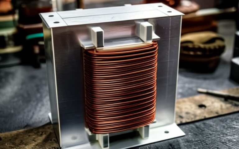
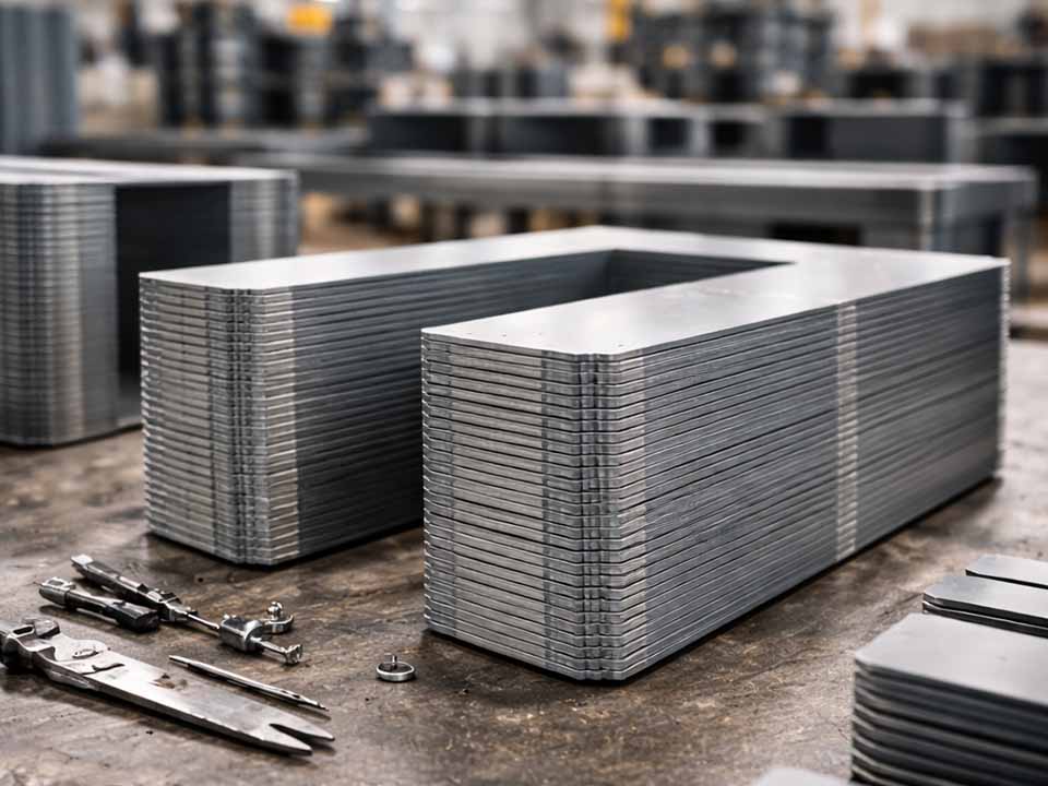
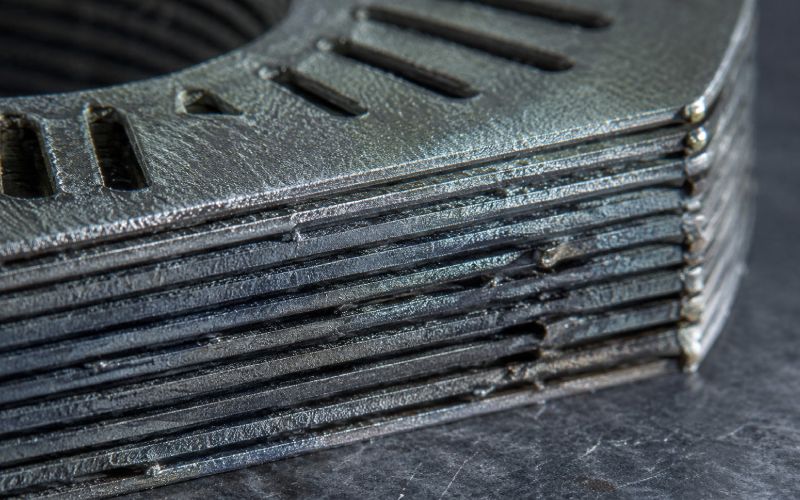
Motor laminations are thin for a reason.
A solid steel core would allow larger eddy current loops. Those loops waste power as heat. Laminated electrical steel breaks the path into thinner layers, and the insulation between sheets helps stop current from jumping from one lamination to the next.
That is the clean version.
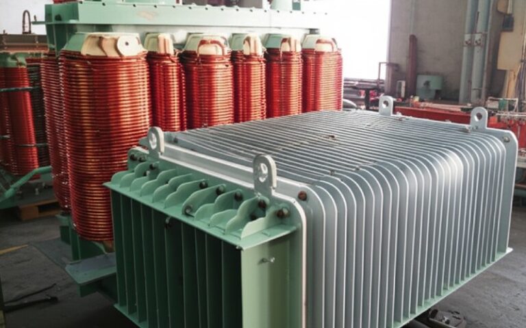
The workshop version is less clean. A coating may be good on the coil. Then the sheet is punched. A burr appears. The stack is pressed. A weld is added. Adhesive cures. The housing fit adds stress. Suddenly, two laminations that should behave as separated sheets are partly connected.
That connection may be small. It may not look serious. But in a stator or rotor core, repeated small shorts can raise core loss, create local heating, and reduce motor efficiency.
So the question is not only:
Does the lamination have an insulating coating?
The better question is:
Does the lamination stack still have enough electrical separation after the real manufacturing process?
That is where interlaminar resistance testing earns its place.
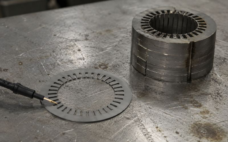
Interlaminar resistance is the electrical resistance between adjacent laminations in a core stack.
In motor laminations, the coating on each sheet should restrict current flow between layers. Higher resistance generally means better isolation. Lower resistance can suggest coating damage, burr contact, contamination, excessive pressure, or conductive paths created during assembly.
A common source of confusion: interlaminar resistance is not the same as surface insulation resistance.
Surface insulation resistance is typically measured on a single strip or punching of electrical steel under defined voltage, pressure, and temperature conditions. Interlaminar resistance is measured between two adjacent coated surfaces, also under controlled conditions, and the result is directly tied to the interface between laminations.
That difference sounds small. In production, it is not.
A single sheet can pass. A stack can still fail.
| Test method | What it checks | Best use | Main limitation |
|---|---|---|---|
| Single-strip surface insulation test | Coating resistance on one lamination face or punching | Incoming material inspection, coating quality control, Franklin-type testing | Does not fully represent two laminations pressed together |
| Two-surface interlaminar resistance test | Resistance between two coated lamination surfaces | Checking coating-to-coating behavior under defined pressure and temperature | May miss edge shorts or local burr contact outside the test area |
| Mini-stack resistance test | Resistance behavior through a small representative stack | Process validation after stamping, bonding, welding, or pressing | Harder to standardize; fixture design matters |
| Finished-core electrical check | Electrical continuity or resistance patterns in an assembled core | Detecting major interlaminar shorts after assembly | May not identify the exact cause |
| Core loss test | Total magnetic loss under excitation | Final performance correlation | Does not isolate coating failure from stress, material grade, or geometry |
No single method covers everything. That is inconvenient, but useful to admit.
A coating test is not a motor test. A core loss test is not a coating test. A burr inspection is not an insulation test. Put them together and the picture becomes much better.
Single-strip surface insulation testing is often used for electrical steel strip, sheet, or punched laminations. The test applies electrical contact to the coated surface under controlled conditions. The goal is to measure how well the surface coating resists current flow.
This method is useful when you need to screen incoming material or compare coating consistency from lot to lot. It is also practical for routine quality control because it is faster than assembling and testing a stack.
Use this method to answer:
“Is the coating on this lamination surface generally acceptable?”
Do not use it alone to answer:
“Will this finished stator or rotor core avoid interlaminar shorts?”
That second question involves punching quality, burr direction, stack pressure, joining method, cleaning, curing, and handling.
Single-strip testing is a good first gate. It is not the whole gatehouse.
Two-surface testing puts two coated electrical steel laminations together and measures resistance through the interface. This is closer to the condition inside a lamination stack.
The method is commonly defined around predetermined voltage, pressure, and temperature. The measured value is resistance, often expressed in kilo-ohms, and it indicates how effectively the coating limits interlaminar current paths in electrical machinery.
This method is especially useful when the coating itself is being qualified or when a process change may affect sheet-to-sheet insulation.
For example:
The important word is controlled.
If pressure changes, the result can change. If temperature changes, the result can change. If the contact area changes, again, the result can change.
That does not make the test weak. It means the test must be described properly.
A resistance value without test pressure, temperature, specimen area, and contact method is only half a result.
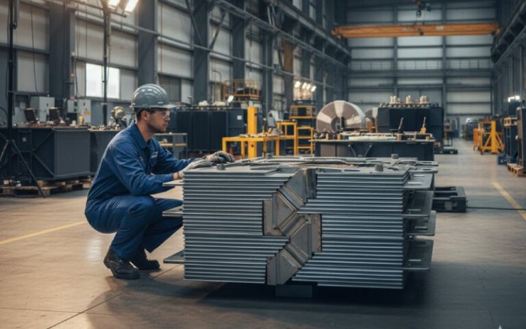
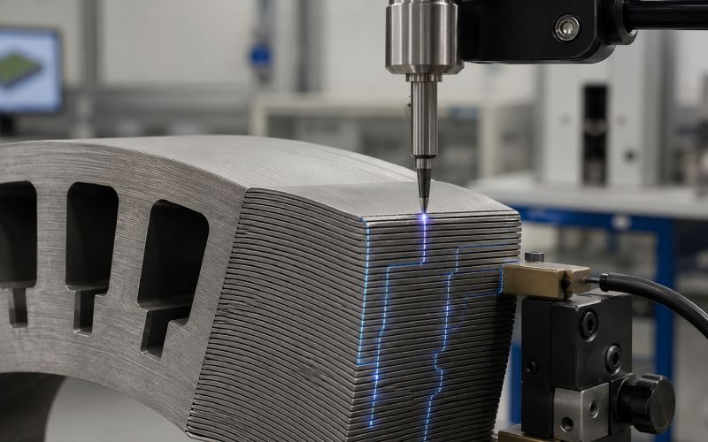
Stack-level testing is not always as neat as a standardized flat-sheet method, but it is often closer to the real problem.
A mini-stack can be built from actual production laminations. Then resistance is checked through selected regions before and after key process steps.
This is where many hidden problems show up.
A lamination may pass coating inspection before punching. After punching, burrs at the edge can create electrical contact between layers. After pressing, the contact becomes stronger. After welding or mechanical joining, some sheets may be electrically bridged. Manufacturing studies have repeatedly linked punching deformation, burr formation, and interlaminar contacts with added eddy-current loss risk in laminated cores.
For motor core quality control, stack-level checks are useful after:
You do not need to test after every step forever. During process development, yes, test more. Once the weak step is known, production control can be simpler.
A good process-specific test plan saves time because it stops chasing the wrong cause.
Low interlaminar resistance usually comes from one of four areas: coating, edge condition, contamination, or assembly pressure.
The coating may be too thin, cracked, uneven, under-cured, over-cured, scratched, or missing in small areas. Even small defects matter if they repeat across many laminations.
Burrs are one of the most common causes of false confidence.
The lamination face may test well. The edge may not. When the stack is compressed, burrs can touch the next sheet and create local conductive paths.
This is why edge inspection and burr height measurement should sit beside electrical testing, not after it as an afterthought.
Metal dust, carbonized residue, dirty oil, abrasive particles, and handling contamination can lower resistance. Sometimes the coating gets blamed when the cleaning process is the real issue.
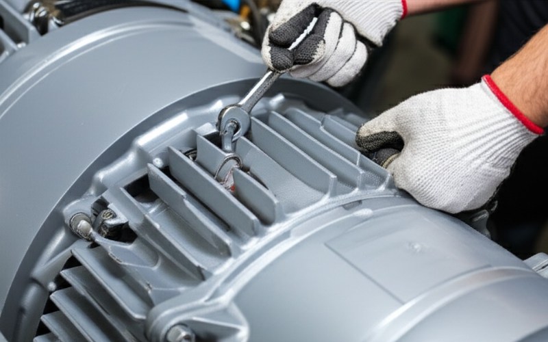
Welding, interlocking, riveting, clamping, and press fitting can create sheet-to-sheet connections. Some are intentional from a mechanical point of view. Electrically, they may add loss if not controlled.
The problem is not always one dramatic short. Often it is many small contacts. Quietly bad.
Interlaminar resistance testing is useful, but it is easy to overread.
A high value does not prove the finished motor core is perfect. It proves the tested interface behaved well under the selected conditions.
A low value does not always mean the coating supplier failed. It may mean the stamping process damaged the coating, the test pressure was too high, the specimen was dirty, or the probe landed on a burr-heavy zone.
The most common mistakes are simple ones:
| Mistake | Why it causes trouble | Better approach |
|---|---|---|
| Testing only flat sheet | Misses process damage from punching or stacking | Test before and after critical manufacturing steps |
| Ignoring burr direction | Burrs may contact adjacent sheets under pressure | Record burr height, direction, and test location |
| Using one reading as proof | Coating and edge quality vary across the lamination | Use multiple readings and track minimum value |
| Comparing results from different fixtures | Pressure and contact area may not match | Fix the test method before setting limits |
| Treating core loss as coating proof | Core loss includes material, stress, geometry, and assembly effects | Use core loss as correlation, not root cause by itself |
A neat number can still tell a messy story.
There is no universal interlaminar resistance limit that works for every motor lamination stack.
A high-speed traction motor, an industrial motor, a generator core, and a small appliance motor do not share the same operating stress. Frequency, flux density, temperature, lamination thickness, coating type, and stack process all matter.
A practical acceptance limit should be built from the application.
Start with these questions:
Then define the test details.
At minimum, record:
For production quality control, the minimum value is often more useful than the average. One weak area can matter more than ten clean readings.
This is where a customized lamination stack test plan is worth using. Not because the test is complicated. Because the wrong test is easy.
A strong inspection plan does not rely on one checkpoint.
Use a layered approach:
Use surface insulation testing to verify coating consistency before stamping or cutting.
Inspect burrs, coating damage, and edge condition. Add electrical checks in areas most likely to short.
Measure coated surface-to-surface behavior under defined pressure and temperature.
Build a small stack using the real manufacturing process. Test before and after bonding, welding, or pressing.
Use core loss testing and thermal checks to confirm whether electrical isolation problems are affecting performance.
This sequence gives a better answer than any single test.
It also helps separate material problems from process problems. That distinction matters when time is being lost between purchasing, production, and quality teams.
Interlaminar resistance readings can drift for reasons that have nothing to do with the lamination.
Review the test setup if you see:
In these cases, the next step is not always “raise the coating requirement.”
Sometimes the right move is better fixture control, better specimen positioning, better burr control, or a test plan that matches the real stack pressure.
For production teams, a controlled test fixture and a clear sampling method usually matter more than adding more random measurements.
Use this checklist before approving a method:
If the answer is no to several of these, the test may still produce numbers. The numbers may not protect the motor.
If your lamination stack shows unstable readings after stamping, bonding, welding, or pressing, the issue may not be the coating alone.
A useful evaluation starts with four details:
From there, a targeted test plan can identify whether the weak point is coating quality, burr formation, stack pressure, contamination, or assembly damage.
That is usually faster than repeating single-sheet tests and hoping the answer appears.
Interlaminar resistance is the resistance to current flow between adjacent laminations in a motor core. It shows how well the insulating coating and stack condition restrict sheet-to-sheet electrical contact.
It helps limit unwanted interlaminar eddy currents. Poor isolation can increase core loss, create local heating, and reduce motor efficiency.
No. Surface insulation resistance is usually tested on one lamination surface or punching. Interlaminar resistance is tested between two adjacent coated surfaces. They are related, but they do not measure the same thing.
A Franklin-type test is commonly used to evaluate surface insulation resistance on electrical steel strip, sheet, or punchings. It is useful for coating quality control and incoming material inspection.
Yes. Stamping burrs, debris, stack pressure, welding, bonding, and handling damage can create conductive paths after the original sheet passes inspection.
Common causes include coating damage, thin coating, burr contact, metal particles, dirty oil, excessive compression, weld paths, interlocking points, and process-related heat damage.
Yes, when burr shorts or edge damage are part of the risk. Face testing and edge-focused testing answer different questions, so the test location should be defined clearly.
There is no fixed number for every stack. Use enough readings to capture variation across the lamination face, edge, tooth area, slot region, bore, and outer diameter. For validation, more readings are better than a clean average from too few points.
No. Core loss also depends on material grade, lamination thickness, flux density, frequency, stress, geometry, joining method, and assembly quality. High resistance helps, but it is not the whole answer.
Use a combined method: surface insulation testing for incoming material, two-surface testing for coating interface behavior, stack-level testing after processing, and core loss testing for final performance correlation.