Let Sino's Lamination Stacks Empower Your Project!
To speed up your project, you can label Lamination Stacks with details such as tolerance, material, surface finish, whether or not oxidized insulation is required, quantity, and more.
A prototype lamination stack can move fast. Not always. But often faster than the first quote suggests.
The delay usually starts before cutting. The drawing is almost ready, the material is “standard,” the stack height is “around 40 mm,” and the team wants it “as soon as possible.” That sounds clear inside the project. To a manufacturer, it is not clear enough to release work.
This playbook is for engineers, buyers, and project owners who need a custom lamination stack for a motor core, stator, rotor, transformer, actuator, generator, or magnetic test build without waiting for full production tooling.
The goal is simple: get a useful prototype built fast, without making decisions that ruin the data later.
For early-stage prototype lamination stacks, the fastest route is usually laser-cut laminations from available electrical steel, followed by simple stacking, welding, bonding, or fixture assembly.
Typical planning ranges look like this:
| Prototype route | Typical lead-time target | Best use case | Main risk |
|---|---|---|---|
| Laser-cut loose lamination set | 3–7 business days | Fit check, winding trial, fixture test | Not a finished stack |
| Laser-cut welded stack | 1–2 weeks | Functional motor core prototype | Heat and local distortion |
| Laser-cut bonded stack | 1–3 weeks | Cleaner assembled stator or rotor core | Adhesive cure and stack height control |
| Wire EDM lamination stack | 1–3 weeks | Tight features, fine slots, small batches | Slower cutting speed |
| Chemically etched laminations | 1–3 weeks | Very thin laminations, fine geometry | Material and thickness limits |
| Prototype stamping or soft tooling | 3–6+ weeks | Pre-production validation | Tooling delay |
| Full production stamping tool | 6–12+ weeks | Stable high-volume design | Expensive if geometry changes |
These are planning ranges, not promises. Material availability, lamination thickness, OD size, feature density, stack height, inspection level, and finishing steps can change the schedule quickly.
Still, the rule holds: if you need speed, avoid hard tooling until the geometry earns it.
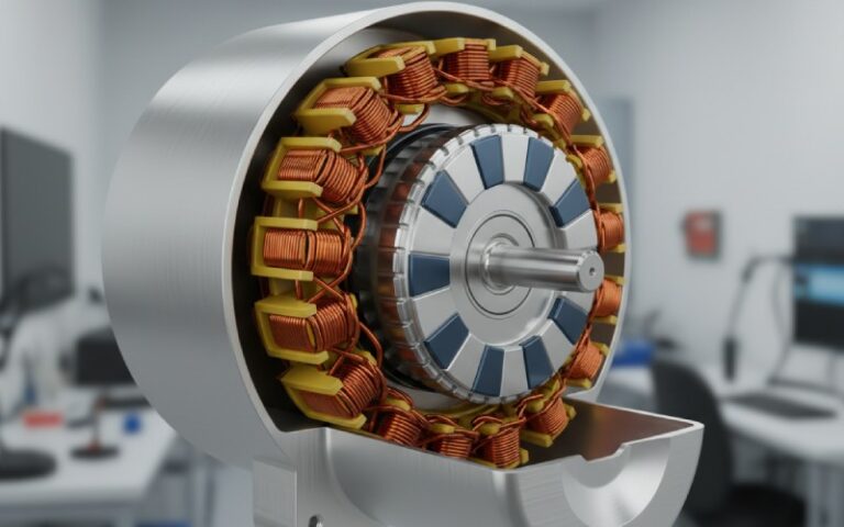
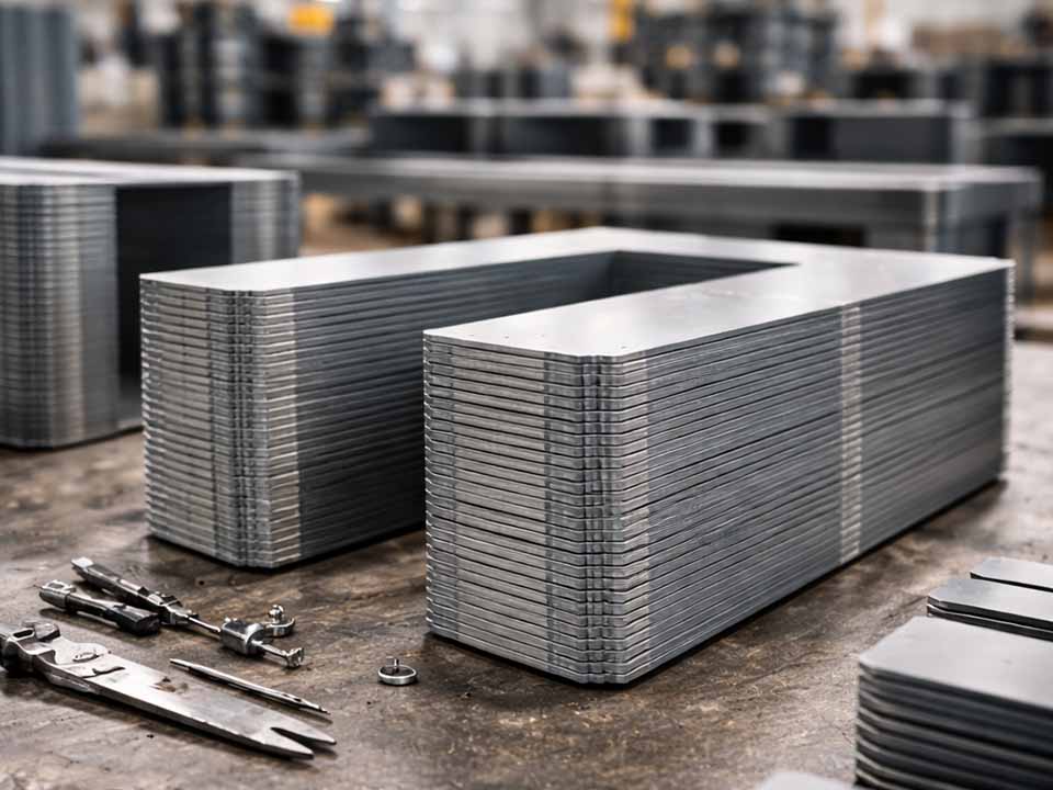
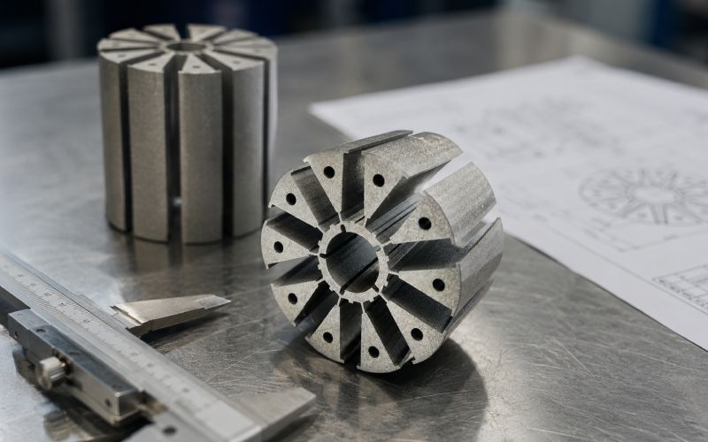
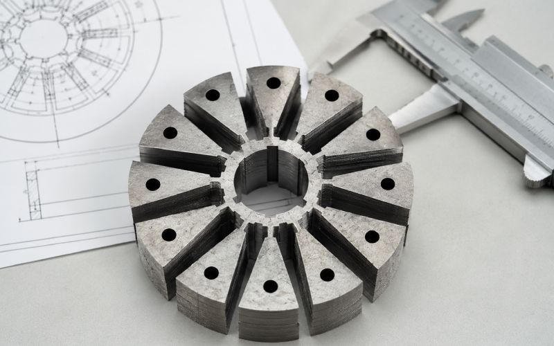
A lamination stack is not just many thin metal sheets.
It is a controlled magnetic assembly. Cutting changes the edge. Burrs affect insulation. Welding changes local heat. Bonding changes stack height. Stress relief changes magnetic behavior. Even the way you measure stack height can cause arguments.
Most slow projects have one of these problems:
| Delay source | Why it slows the build | Fast fix |
|---|---|---|
| Undefined material | Supplier must confirm grade, coating, and thickness | Give preferred and acceptable substitute materials |
| No DXF/DWG file | PDF-only drawings create programming delays | Send clean 2D cutting files |
| Every dimension marked critical | Inspection becomes too heavy | Mark only functional dimensions as critical |
| Unknown stack method | Assembly quote cannot be finished | Choose loose, welded, bonded, pinned, or clamped |
| No burr requirement | Rework risk increases | Define burr direction and maximum burr if needed |
| Vague stack height | Lamination count and compression are unclear | State target height and measurement condition |
| Production intent too early | Tooling and process reviews add weeks | Use no-tool prototype route first |
A fast prototype starts with a narrow question. “Can this slot be wound?” is narrow. “Can this design become our final production motor core?” is not.
Before choosing laser cutting, wire EDM, bonding, welding, or stamping, decide what the stack is supposed to prove.
Do not skip this. It saves days.
| Prototype goal | Optimize for | You can usually relax |
|---|---|---|
| Mechanical fit | OD, ID, bolt holes, shaft fit, stack height | Final magnetic loss |
| Winding trial | Slot opening, tooth shape, insulation clearance | Final joining method |
| Spin test | Concentricity, balance, rotor retention | Cosmetic edge finish |
| Thermal test | Stack contact, housing fit, winding fill | Perfect magnetic grade |
| Magnetic test | Steel grade, cutting method, burr control, stress relief | Fastest possible build |
| Customer sample | Clean assembly, safe handling, visual finish | Full production economics |
A geometry prototype and a magnetic validation prototype should not use the same rules.
That sounds obvious. It gets missed constantly.
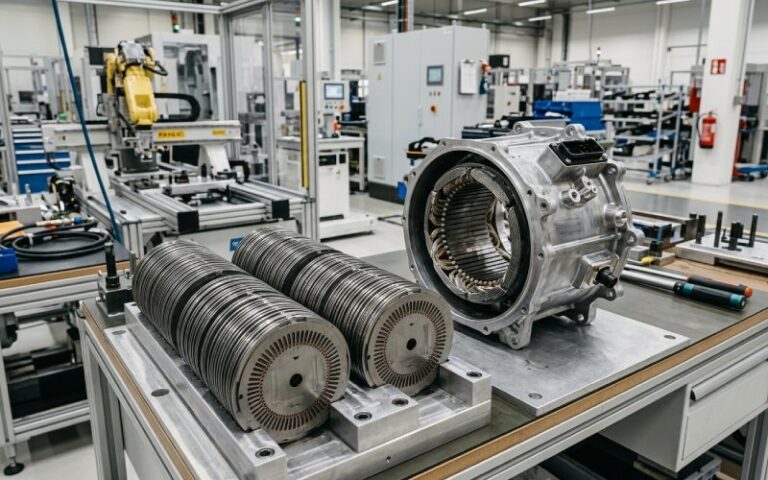
Laser cutting is usually the fastest path for a prototype lamination stack because it needs no dedicated stamping tool. It is well suited for custom stator laminations, prototype rotor laminations, electrical steel lamination samples, and fast motor core prototyping.
Use laser cutting when:
Watch the edge condition. Laser cutting can create heat-affected zones and stress near the cut edge. For a fit prototype, that may not matter. For a core loss study, it may matter a lot.
Bottom line: choose laser cutting when speed and geometry flexibility matter more than final magnetic certainty.
Wire EDM is slower than laser cutting in many cases, but it can be useful when the lamination has narrow bridges, fine slot features, small radii, or tight profile requirements.
Use wire EDM when:
Wire EDM is not magic. It still needs programming, fixturing, and inspection. But for fine-feature prototypes, it can prevent the “fast but wrong” problem.
Bottom line: choose wire EDM when accuracy is worth more than the shortest calendar time.
Stamping makes sense when the design is stable and the expected volume justifies tooling. For the first lamination stack prototype, stamping is often too slow and too expensive.
Use stamping when:
Bottom line: stamping is excellent after the design settles. It is usually a poor first move when the drawing is still changing.
If you want a short lead time, send a complete manufacturing pack. Not a half-pack with notes scattered across email threads.
A useful RFQ pack for a prototype lamination stack includes:
| RFQ item | What to send |
|---|---|
| Lamination geometry | DXF or DWG file, plus PDF drawing |
| Stack model | STEP file if available |
| Application | Stator, rotor, transformer, actuator, generator, test coupon |
| Material | Electrical steel grade, thickness, coating, allowed substitutes |
| Quantity | Number of stacks, spare laminations, test coupons |
| Stack height | Target height and tolerance |
| Lamination count | Fixed count or adjusted to target height |
| Cutting method | Laser, wire EDM, etching, stamping, or open to recommendation |
| Stacking method | Loose, welded, bonded, riveted, pinned, clamped |
| Burr requirement | Max burr, burr direction, deburring allowed or not |
| Heat treatment | Required, optional, or not allowed |
| Critical dimensions | Bore, OD, slot, tooth, magnet pocket, datum features |
| Inspection | Basic dimensional check or full report |
| Timeline | Required ship date and flexible items |
Here is the small but useful phrase to add:
“If any requirement increases lead time, please identify it separately.”
That one sentence can expose the real blocker. Maybe it is not the cutting. Maybe it is the material. Maybe it is one over-tight tolerance on a non-critical feature.
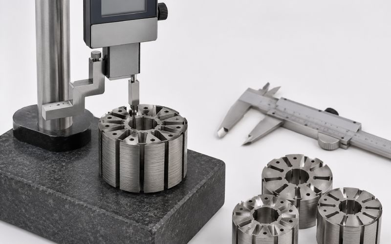
Stack height causes more trouble than it should.
A lamination stack is made from coated sheets. The coating, burrs, flatness, pressure, bonding layer, weld distortion, and sheet thickness variation all affect final height. So “40 mm stack height” is not enough.
Specify stack height like this:
Target stack height: 40.00 mm ±0.10 mm, measured under defined compression after stacking.
Or, if lamination count matters more:
Build with 120 laminations. Final stack height to be reported, not adjusted.
Those are different builds.
For fast prototypes, choose one priority:
You may want all four. Fine. But one should lead.
The stacking method changes the prototype’s stiffness, handling, magnetic behavior, and delivery time.
| Stacking method | Speed | Best for | Watch-out |
|---|---|---|---|
| Loose stack | Fastest | Fit checks, winding trials, lab fixtures | Poor handling |
| Clamped stack | Fast | Magnetic coupons, temporary testing | Fixture affects result |
| Welded stack | Fast | Rigid prototype motor cores | Heat and local shorting risk |
| Bonded stack | Medium | Cleaner stack, less metal joining | Cure time and adhesive thickness |
| Riveted or pinned stack | Medium | Mechanical alignment | Extra holes may affect flux path |
| Interlocked stack | Slower for prototypes | Production-style validation | Usually needs tooling or added features |
For a quick-turn stator lamination stack, welding may be acceptable if the test is mechanical or thermal. For a magnetic loss test, bonding or controlled clamping may give cleaner data.
No single method is best. The test decides.
This is where prototypes get heavy.
A first build does not always need final coating approval, final joining method, full inspection, final steel grade, stress relief, and perfect cosmetics. Some do. Most do not.
A faster first build may allow:
Do not relax the bore if it controls shaft fit. Do not relax slot opening if winding access is the test. Do not relax magnet pocket geometry if retention is the question.
Relax the things that do not answer the current question.
Order extra laminations. Always.
Prototype laminations get scratched, bent, dropped, over-pressed, mis-stacked, or consumed in inspection. A winding trial can damage a tooth. A rotor trial can expose a burr issue. A bonded stack may need a section cut.
A good prototype order often includes:
This adds a small cost. It can save a second procurement cycle.
Use this three-stage path when the project is urgent and the design is still moving.
Purpose: fit, assembly, winding access, housing clearance.
Best route: laser-cut available material, loose or lightly fixed stack.
Lead-time target: days to about one week.
Do not use this build to make final efficiency claims.
Purpose: winding, thermal test, spin test, early electrical test.
Best route: closer material, controlled burr direction, welded or bonded assembly.
Lead-time target: one to three weeks.
This is where most design mistakes show up.
Purpose: core loss, efficiency, material comparison, simulation correlation.
Best route: locked material, controlled cutting method, defined stress relief decision, documented inspection.
Lead-time target: longer, because the data matters.
This staged plan feels slower on paper. It often wins in real projects because the first build catches simple errors before the expensive build starts.
If you need a quick-turn prototype lamination stack, prepare this short package:
A fast review is only possible when the file tells the truth. If the design is still rough, say so. A rough design can still be quoted, but it should not be treated like a released drawing.
Production quality needs production rules. Material locked. Tooling path known. Inspection defined. Joining method chosen. If those decisions are not ready, the phrase adds confusion.
Burrs can affect stacking, insulation, local shorting, and measurement repeatability. For magnetic prototypes, burr control is functional.
Changing from one electrical steel grade or thickness to another can change stack height, lamination count, cutting behavior, coating, and magnetic performance. That is not a small edit.
One prototype cannot answer everything equally well. A fast fit stack is not automatically a magnetic validation stack.
A 3D model helps, but lamination cutting usually needs clean 2D profile data. Send both if possible.
A simple laser-cut lamination set can often be planned in days. A finished welded or bonded stack is more commonly planned around one to three weeks. Tooling-based prototypes can take several weeks or more. The exact time depends on material, thickness, geometry, stack height, finishing, and inspection.
Laser cutting is usually faster for quick-turn stator laminations and rotor laminations. Wire EDM is often better for small batches with tight tolerances, fine features, or delicate profiles. Choose laser cutting for speed. Choose wire EDM for detail control.
Yes, but the test type matters. Laser-cut laminations are useful for fit, winding, thermal, spin, and early functional tests. For final magnetic validation, edge effects, burrs, stress, and heat treatment decisions need closer control.
Send a DXF or DWG file, a PDF drawing, material details, target stack height, lamination count if fixed, quantity, stacking method, burr requirements, and inspection needs. A STEP file is helpful for assembly context.
A loose or clamped stack is usually fastest. A welded stack is often the fastest rigid assembly. Bonding can produce a cleaner stack but may add cure time and height-control steps.
Not always. Stress relief is useful when magnetic performance, core loss, or simulation correlation matters. For fit checks and winding trials, it may not be necessary.
Choose exact stack height when the prototype must fit a housing or meet an active length target. Choose exact lamination count when the magnetic design or test comparison depends on the number of sheets. If both matter, define the priority.
Send clean cutting files, allow available material substitutes for early builds, mark only true critical dimensions, choose a simple stacking method, define burr direction, and include the prototype’s test purpose in the RFQ.
Build the first prototype lamination stack to answer the nearest expensive question.
If the expensive question is fit, build for fit. If it is winding, build for winding. If it is magnetic loss, slow down and control the process.
Fast does not mean careless. It means removing the decisions that do not matter yet, so the few that do matter get handled correctly.