Biarkan Tumpukan Laminasi Sino Memberdayakan Proyek Anda!
Untuk mempercepat proyek Anda, Anda dapat melabeli Tumpukan Laminasi dengan detail seperti toleransi, bahan, permukaan akhir, apakah isolasi teroksidasi diperlukan atau tidak, kuantitasdan banyak lagi.
Penyebab utama pergeseran kinerja laminasi CRGO dalam batch produksi
Anda memesan Laminasi CRGO dengan grade yang sama, lapisan yang sama, gambar yang sama. Namun, kehilangan tanpa beban mencapai 8%. Arus magnetisasi merayap di luar lembar kerja desain Anda. Pergeseran kebisingan.
“Spesifikasi yang sama, hasil yang berbeda.” Artikel ini membahas tentang kesenjangan itu.
Daftar Isi
1. Spesifikasinya sudah pasti. Prosesnya tidak.
Di atas kertas, sekumpulan laminasi CRGO ditentukan oleh:
kelas (mis. M3, HI-B, domain-disempurnakan, dll.)
ketebalan nominal
kelas pelapis / isolasi
kehilangan inti dan permeabilitas Epstein yang terjamin
Yang kurang terlihat adalah sebarannya di dalam jendela toleransi pabrik dan bagaimana proses pemotongan, pemotongan, penumpukan, dan anil Anda memperkuat atau meredam sebaran tersebut. Baja berorientasi butiran sangat sensitif terhadap struktur; pergeseran kecil dalam hal kimia, tekstur, ukuran butiran, dan tekanan internal memberikan perubahan yang terukur dalam hal kehilangan dan permeabilitas.
Jadi, dua batch yang sama-sama “memenuhi spesifikasi” dapat menghasilkan core yang sangat berbeda setelah Anda melubangi, menumpuk, dan menjepitnya. Itulah inti dari pergeseran kinerja.
Mari kita telusuri rantainya, dari lempengan hingga tumpukan laminasi yang sudah jadi.
2. Variasi sisi gilingan di dalam gulungan “baik”
2.1 Jendela kimia dan sistem penghambat
Bahkan dalam satu grade, pabrik menyetel Si, Al, C, N dan spesies inhibitor (MnS, AlN, dll) untuk mendorong rekristalisasi sekunder dan tekstur Goss. Pergeseran kecil di sini memengaruhi distribusi ukuran butir dan sifat magnetik akhir.
Anda melihatnya sebagai:
Variasi koil-ke-koil dalam kehilangan Epstein, masih dalam jaminan
Kemiringan kurva B-H yang sedikit berbeda
Sensitivitas yang berbeda terhadap kondisi pelubangan dan anil Anda
Dua kumparan dari heat yang berbeda, dengan nilai nominal yang sama, tidak akan merespons secara identik pada garis yang sama.
2.2 Tekstur, ukuran butir, dan rekayasa domain
Ketajaman tekstur dan distribusi ukuran butir menentukan kehilangan dasar dan permeabilitas. Penelitian terus menunjukkan bahwa perubahan kecil pada kondisi rekristalisasi, dispersi inhibitor, dan suhu anil dapat menggeser tekstur dan perilaku pertumbuhan butir, yang kemudian berimbas langsung pada kehilangan inti.
Anda tidak dapat sepenuhnya “memperbaiki” hal tersebut di bagian hilir, hanya saja Anda dapat menghindari memperburuk keadaan.
2.3 Variasi kelas pelapisan dan isolasi
ASTM A976 C-class (C-0... C-6) berbeda dalam hal kimia, ketahanan isolasi, gesekan, dan perilaku pelepas tegangan yang diinginkan.
Dua hal terjadi:
Respons menggorok / meninju - pelapis dengan gesekan yang berbeda mengubah tegangan strip dan bagaimana bentuk duri dan rollover.
Perilaku tumpukan - resistensi isolasi dan ketebalan lapisan mengubah faktor laminasi dan kehilangan interlaminar.
Jika Anda mengganti pemasok atau kelas pelapis “tetapi mempertahankan yang lainnya”, penyimpangan batch hampir pasti terjadi.
3. Belah: kualitas tepi adalah variabel tersembunyi pertama Anda
Pada saat strip meninggalkan slitter, banyak drift yang kemudian sudah terpanggang.
3.1 Tinggi duri dan regangan tepi
Duri yang tinggi dan guling yang berat bukan sekadar kosmetik. Mereka:
mengurangi faktor penumpukan
membuat celana pendek mikro di antara laminasi
menyuntikkan tegangan lokal tepat di tempat fluks berkumpul di tepinya
Hal ini menimbulkan rugi arus pusar lokal dan rugi histeresis dan sering muncul sebagai rugi inti yang lebih tinggi dan inti yang lebih berisik. Pengalaman industri dan studi laminasi motor/transformator secara konsisten menghubungkan gerinda yang lebih tinggi dengan kerugian yang lebih tinggi dan efisiensi yang lebih buruk.
Duri ikut terbawa arus:
ketajaman dan jarak bebas pisau
pengaturan dan ketegangan garis penggorok
kekerasan dan pelapisan strip (dari bagian 2)
Jadi, bets yang kebetulan terpotong pada akhir kurva umur pisau, secara diam-diam akan berkinerja lebih buruk.
3.2 Camber dan sebaran lebar
Strip camber, gelombang tepi, dan variasi lebar biasanya “masih dalam toleransi” sampai Anda mulai menumpuk dan melihatnya:
celah pangkuan langkah tidak duduk berulang kali
tekanan penjepitan yang tidak merata
celah udara mikro acak di dalam tumpukan
Semuanya muncul sebagai arus magnetisasi yang lebih tinggi dan terkadang “misteri” kehilangan tanpa beban yang melayang.
3.3 Pilihan teknologi pemotongan
Saat desain bergerak ke arah pengukur yang lebih tipis dan geometri yang lebih kompleks, proses pemotongan itu sendiri menjadi variabel yang nyata. Geser mekanis, bentukan, pemotongan laser, dan garis pemotongan inti yang canggih memberlakukan status tegangan yang berbeda dan zona yang terpengaruh panas pada bagian tepi.
Satu potongan batch pada jalur press mekanis yang lebih tua dan yang lain pada jalur cut-to-length yang lebih baru dapat diuji secara berbeda bahkan dengan kumparan dan gambar yang identik.
4. Melubangi dan membuat bentukan: dari lembaran hingga laminasi
Sekarang strip menjadi beberapa bagian. Setiap pengaturan alat dan pers mulai berarti.
4.1 Pengaturan keausan alat dan pers
Saat pukulan dipakai:
tinggi duri merayap naik
rollover memburuk
retak mikro muncul di tepi slot
Ketinggian tekan, jarak bebas die, pelumasan, dan kecepatan bergerak seiring dengan perubahan yang dilakukan orang untuk mendapatkan hasil. Variasi sehari-hari di sini adalah salah satu alasan dunia nyata yang paling umum untuk penyimpangan kinerja laminasi. Hal ini jarang sekali muncul di lembar data, tetapi Anda akan melihatnya di foto mikroskop dan kehilangan inti.
4.2 Kesalahan arah butir dan orientasi campuran
CRGO bergantung pada arah penggulungan yang sejajar dengan jalur fluks utama Anda. Orientasi yang salah (bahkan sebagian laminasi yang diputar 90°) secara dramatis meningkatkan kehilangan lokal dan arus magnetisasi.
Dalam produksi, hal ini bisa terjadi apabila:
kumparan dimuat mundur pada sebuah garis
alat blanking digunakan bersama di antara bagian yang berbeda dan pergeseran pengaturan
operator mencampur bagian “kiri” dan “kanan” dari dua sarang yang berbeda
Batch terlihat baik-baik saja secara visual. Bangku tes tidak setuju.
4.3 Penyebab stres lokal
Sudut-sudut bagian dalam yang tajam, lubang pilot yang terlalu rapat, dan pembentukan yang berat semuanya memusatkan tegangan. GOES cukup sensitif; tegangan lokal menggeser kurva B-H dan magnetostriksi. Bahkan jika gambar Anda identik, penyesuaian penekanan yang halus akan mengubah seberapa keras Anda “bekerja” pada baja, dan dengan demikian, kerugiannya.
5. Penumpukan, geometri sambungan, dan penjepitan
Anda bisa merusak laminasi yang bagus dengan penumpukan yang ceroboh, atau membuat bahan yang biasa-biasa saja terlihat dapat diterima dengan penumpukan yang disiplin. Hal itu saja sudah menunjukkan kepada Anda, betapa kuatnya hubungan ini.
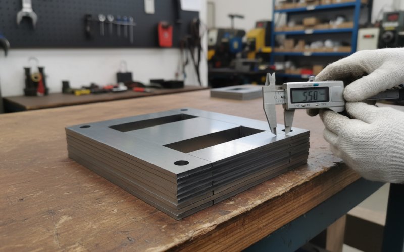
5.1 Penyimpangan faktor laminasi
Standar dan katalog pabrik berbicara tentang faktor laminasi (faktor penumpukan) untuk tumpukan yang rapi dan ideal. Tumpukan yang sesungguhnya, dengan duri dan lapisan, jarang sekali menyamainya.
Pengemudi:
variasi ketebalan lapisan
tinggi duri dan deformasi tepi
metode penumpukan (manual vs robot, konsistensi interleaving)
Jika model CAD Anda mengasumsikan besi 100% dan faktor laminasi aktual bergeser dari 96% ke 93%, kerapatan fluks bergerak, dan begitu pula dengan kehilangan dan arus magnetisasi.
5.2 Akurasi T-joint dan step-lap
Distribusi kehilangan lokal pada sambungan-T dan tumpang tindih sangat bergantung pada sudut tumpang tindih, panjang, dan pola lapisan. Studi menunjukkan bahwa kehilangan inti lokal meningkat dari tepi luar ke dalam pada step-lap sudut campuran ketika penyelarasan tidak aktif.
Sumber-sumber penyimpangan dalam kehidupan nyata:
tim perakitan yang berbeda menggunakan kebiasaan melangkah yang sedikit berbeda
perlengkapan yang dipakai dari waktu ke waktu, sehingga kemasan dapat bergeser
desain inti baru yang menggunakan kembali perlengkapan susun lama “yang cukup dekat”
Anda akan mendapatkan bill of material yang sama, tetapi gambar fluks lokal yang berbeda.
5.3 Tekanan penjepitan dan desain rangka
Core yang tidak dijepit akan berdengung dan bergerak. Core yang terlalu banyak dijepit memiliki tekanan mekanis ekstra dan dapat menunjukkan kerugian yang lebih tinggi. Penjepitan yang tidak merata menciptakan kinerja yang bervariasi secara spasial: beberapa kaki berjalan lebih dekat ke spesifikasi, beberapa lebih buruk.
Pergeseran batch muncul ketika:
perubahan urutan torsi
desain rangka direvisi tanpa perubahan yang sesuai dalam batas pengujian
bantalan atau insulasi di bawah kuk memampatkan secara berbeda karena perubahan material
6. Anil penghilang stres: pengganda yang tenang
Anil pelepas stres adalah salah satu pengungkit terkuat pada kinerja CRGO, karena mengendurkan pekerjaan dingin dari menggorok, meninju, dan menumpuk. Banyak lembar data mengasumsikan strip dianil pelepas stres saat mengutip nilai kerugian terbaik.
Drift muncul apabila proses yang sesungguhnya menyimpang:
pemuatan tungku menjadi lebih padat dari waktu ke waktu
waktu rendam dipangkas untuk mendapatkan hasil
usia termokopel, sehingga suhu laminasi yang sebenarnya berubah tanpa ada yang memperhatikan
ukuran inti yang berbeda memiliki siklus yang sama, meskipun massa termal tidak sama
Hasilnya: satu bulan prosesnya benar-benar mengurangi stres; satu bulan lagi hanya setengahnya saja.
Tes inti yang telah selesai akan mencerminkan hal tersebut.
Ada juga masalah “kerusakan setelah anil” yang tidak kentara:
mengelas atau menggiling di dekat inti
penanganan kasar dan pembengkokan kuk
peening lokal dari perlengkapan
Semua menambah tekanan baru setelah Anda membayar tungku.
7. Penanganan, penyimpanan, dan pencampuran bahan
Bagian ini terasa biasa saja. Sebenarnya tidak.
7.1 Mencampur nilai atau tingkat kualitas
Beberapa pasar melihat impor material CRGO “detik dan cacat”, yang memiliki kontrol yang lebih longgar pada kerataan, duri, camber, dan properti. Suara-suara dari industri telah menyoroti bagaimana duri tepi dan camber pada material tersebut secara langsung memperburuk faktor penumpukan dan kehilangan inti.
Jika pabrik laminasi Anda sesekali mengisi ulang dengan jenis bahan ini ketika stok utama menipis, pergeseran batch-ke-batch tidak dapat dihindari, meskipun tingkat papan nama tetap sama.
7.2 Karat, kelembapan, dan kerusakan lapisan
Penyimpanan yang buruk - kelembapan tinggi, kondensasi, penumpukan yang kasar - bisa:
mengurangi resistensi insulasi antara laminasi
merusak atau mengupas lapisan
menimbulkan lubang korosi dan kekasaran permukaan
Semuanya diterjemahkan ke dalam kehilangan interlaminar yang lebih tinggi dan terkadang meningkatkan noise.
7.3 Menggunakan kembali atau mengerjakan ulang laminasi
Proses laminasi ulang, penggilingan ulang, atau penumpukan ulang dari core yang ditolak atau proses prototipe akan menghemat baja dalam jangka pendek dan menimbulkan ketidakkonsistenan dalam jangka panjang. Setiap langkah penanganan ekstra menambah tekanan, kemungkinan goresan melalui lapisan, dan penyebaran geometri.
8. Pengukuran dan ilusi spesifikasi
Banyak hal yang diberi label “penyimpangan performa” dapat ditelusuri kembali ke cara Anda membandingkan data pengujian dengan data pabrik.
8.1 Tes Epstein vs realitas inti yang dibangun
Jaminan pabrik biasanya didasarkan pada strip Epstein: anil pelepas stres, orientasi butiran yang ideal, jalur magnetik yang sederhana.
Inti rakitan Anda adalah:
meninju
ditumpuk dengan duri dan lapisan asli
dijepit dalam bingkai
terkadang hanya menghilangkan sebagian stres
Membandingkan hasil-hasil tersebut satu per satu akan selalu menunjukkan kesenjangan. Yang penting adalah bagaimana kesenjangan itu berubah seiring waktu.
Jika proses Anda menambahkan “penalti” yang kira-kira konstan ke hasil Epstein, drift rendah. Ketika proses Anda sendiri menyebar, drift tinggi. Banyak perusahaan tidak melacak delta ini secara eksplisit, yang membuat akar penyebabnya bekerja lebih lambat.
8.2 Penyimpangan pengaturan uji
Bahkan laboratorium yang bagus pun mengalami perubahan:
kalibrasi kerapatan fluks
suhu inti selama pengujian tanpa beban
penempatan sensor dan perutean kabel
Kehilangan tanpa beban sensitif terhadap induksi, frekuensi, dan suhu, dan suhu saja dapat secara nyata mengubah kehilangan pada GOES.
Sebelum menyalahkan laminasi, ada baiknya memastikan bahwa test bench, kabel, dan perangkat lunaknya tidak berubah.
9. Referensi cepat: gejala umum vs kemungkinan penyebab utama
Gunakan tabel ini sebagai filter awal ketika satu batch tumpukan laminasi CRGO berperilaku berbeda dari sebelumnya.
Gejala dalam tes rutin / FAT
Kemungkinan penyebab cluster
Hal-hal cepat yang harus diperiksa terlebih dahulu
Perbaikan jangka menengah
Kehilangan tanpa beban +5-10% vs batch terakhir, arus magnetisasi juga lebih tinggi
Peningkatan duri, pelepasan tegangan yang lebih buruk, penurunan faktor laminasi
Ukur tinggi duri pada batch saat ini vs batch sebelumnya; periksa data pemuatan dan perendaman tungku
Kencangkan batas duri di PO; tentukan pukulan pahat maksimal per penajaman; memenuhi syarat resep tungku per ukuran inti
Kehilangan tanpa beban naik, arus magnetisasi kira-kira tidak berubah
Kehilangan lokal pada sambungan, masalah pelapisan/insulasi
Termografi pada inti yang sedang diuji; cari sambungan panas; periksa kelas pelapisan atau perubahan pemasok
Menstandarkan pola step-lap dan perlengkapan susun; mengunci spesifikasi insulasi dan tes masuk
Arus magnetisasi naik, kehilangan hanya sedikit naik
Perubahan faktor laminasi, kesalahan orientasi butir, perubahan pola penjepitan
Timbang tumpukan vs teoritis; verifikasi tanda arah penggulungan; periksa riwayat torsi penjepitan
Tentukan uji faktor laminasi; tambahkan poka-yoke untuk arah butiran pada garis; mendesain ulang bingkai untuk tekanan yang lebih berulang
Peningkatan kebisingan hanya dengan sedikit perubahan kerugian
Distribusi tegangan, penjepitan, anil parsial
Dengarkan dengungan lokal, periksa titik kontak rangka; tinjau catatan tungku untuk batch tersebut
Meningkatkan penyangga inti dan redaman; menyetel penjepitan; meninjau operasi pasca-anneal (pengelasan, penggerindaan)
Variasi yang besar antara core yang dibuat dari batch laminasi yang sama
Variasi perakitan dan penumpukan, penyimpangan pengaturan pengujian
Bandingkan geometri tumpukan, pola sambungan, dan log torsi; periksa silang bangku uji dengan inti referensi
Menstandarkan instruksi kerja; mengotomatiskan atau memperbaiki lebih banyak penumpukan; menambahkan pemeriksaan kalibrasi meja uji secara teratur
10. Membuat kinerja laminasi CRGO lebih stabil dengan sengaja
Anda tidak dapat menghilangkan semua variasi pada baja elektrik berorientasi serat. Tetapi Anda dapat mendesain pasokan laminasi dan produksi inti sehingga sebagian besar variasi berada di bagian hulu dan transparan, tidak tersembunyi di dalam pabrik Anda.
Gerakan khas yang membantu:
Tentukan batas yang terkait dengan proses, bukan hanya nilai
tinggi duri maksimal dan metode pengukuran
uji penerimaan faktor laminasi pada tumpukan sampel
kelas dan pemasok pelapis yang diizinkan
Melacak silsilah koil-ke-inti
mengetahui inti transformator mana yang menggunakan kumparan mana dan pengaturan jalur mana
ketika sebuah batch melayang, Anda dapat melihat apakah batch tersebut mengelompok di sekitar koil, alat, atau beban tungku
Korelasikan “tanda tangan proses” Anda sendiri dengan data pabrik
menyimpan satu set kecil inti uji standar yang dibuat dengan cara yang sama dari setiap batch laminasi
bandingkan penalti Anda vs angka Epstein pabrik dari waktu ke waktu
Perlakukan pemotongan dan anil sebagai parameter desain, bukan hanya utilitas produksi
ketika desain beralih ke pengukur yang lebih tipis atau target kehilangan yang lebih ketat, tinjau apakah jalur dan tungku yang ada masih sesuai
Dilakukan secara sistematis, hal ini mengubah “misteri penyimpangan” menjadi seperangkat variabel yang terkendali.
FAQ: pertanyaan umum tentang penyimpangan batch laminasi CRGO
1. Berapa tingkat variasi dalam kehilangan inti di antara batch laminasi yang dapat diterima secara realistis?
Anda tidak akan pernah mendapatkan penyebaran nol. Banyak OEM transformator memperlakukan variasi ± 3-5% dalam kehilangan tanpa beban antara batch (pada desain dan kondisi pengujian yang konstan) sebagai hal yang normal. Lebih ketat dari itu biasanya membutuhkan pemotongan, pelubangan, dan anil yang sangat terkontrol, ditambah kemitraan pabrik yang baik. Ketika hasilnya berada di luar batas tersebut, ini merupakan tanda untuk memeriksa perkakas, proses tungku, dan catatan material yang masuk.
2. Apakah tinggi duri benar-benar penting jika resistansi insulasi saya tinggi?
Ya, duri adalah proksi untuk regangan tepi dan distorsi geometri lokal, tidak hanya untuk short turn-to-turn. Bahkan jika insulasi masih utuh, duri yang tinggi meningkatkan kerapatan fluks lokal dan menimbulkan tegangan sisa, yang keduanya meningkatkan kerugian. Studi dan pengalaman industri menghubungkan tingkat duri yang lebih tinggi dengan kehilangan inti yang lebih tinggi dan faktor penumpukan yang lebih buruk.
3. Dapatkah saya “memperbaiki” kumpulan laminasi dengan tingkat kehilangan yang lebih tinggi dengan anil pelepas tegangan yang lebih lama?
Kadang-kadang Anda dapat mengurangi penalti, tetapi Anda tidak dapat mengubah tekstur dan kimia yang mendasarinya. Penghilang stres terutama menghilangkan stres pemrosesan dari pemotongan dan penumpukan. Jika kehilangan yang lebih tinggi disebabkan oleh perbedaan sisi pabrik (ukuran butir, distribusi inhibitor, ketajaman tekstur), anil tidak akan membuat bets identik dengan koil yang lebih baik; itu hanya membuat kontribusi Anda lebih konsisten.
4. Apakah perlu menentukan kerugian Epstein yang lebih ketat daripada tingkat standar?
Bisa saja, tetapi hanya jika Anda juga mengontrol proses internal Anda. Spesifikasi pabrik yang lebih ketat mengurangi sebaran kumparan-ke-kumparan, yang membantu. Jika variasi Anda sendiri dari burr, penumpukan, dan anil lebih besar daripada sebaran pabrik, Anda tidak akan melihat peningkatannya. Jalur yang biasa dilakukan adalah: menstabilkan proses internal → kemudian menegosiasikan toleransi pabrik yang lebih ketat yang benar-benar diterjemahkan ke dalam penyebaran yang lebih rendah di tingkat inti.
5. Seberapa sering kita harus melakukan kualifikasi ulang alat potong dan proses penumpukan untuk laminasi CRGO?
Pikirkanlah dalam hal data, bukan kalender. Lacak: tinggi duri vs goresan pada setiap alat kehilangan inti vs usia alat dan vs beban tungku variasi antara operator atau shift dalam penumpukan Setelah Anda melihat di mana kinerja mulai menurun, tetapkan batas pemeliharaan preventif atau kualifikasi ulang sebelum titik tersebut. Bagi banyak pabrik, hal ini akhirnya dikaitkan dengan jumlah pukulan dan kurva pertumbuhan duri yang terukur, bukannya “setiap X bulan”, karena volume produksi dan campuran material bervariasi.
Cheney adalah seorang Senior Application Engineer yang berdedikasi di Sino, dengan hasrat yang kuat untuk manufaktur presisi. Dia memiliki latar belakang di bidang Teknik Mesin dan memiliki pengalaman manufaktur yang luas. Di Sino, Cheney berfokus pada pengoptimalan proses manufaktur tumpukan laminasi dan menerapkan teknik inovatif untuk mencapai produk tumpukan laminasi berkualitas tinggi.
Brosur Produk Baru
Silakan masukkan alamat email Anda di bawah ini dan kami akan mengirimkan brosur terbaru kepada Anda!
Biarkan Tumpukan Laminasi Sino Memberdayakan Proyek Anda!
Untuk mempercepat proyek Anda, Anda dapat melabeli Tumpukan Laminasi dengan detail seperti toleransi, bahan, permukaan akhir, apakah isolasi teroksidasi diperlukan atau tidak, kuantitasdan banyak lagi.