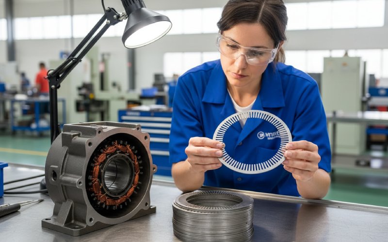
Lasciate che le pile di laminazione di Sino diano forza al vostro progetto!
Per velocizzare il progetto, è possibile etichettare le pile di laminazione con dettagli quali tolleranza, materiale, finitura superficiale, se è necessario o meno un isolamento ossidato, quantitàe altro ancora.
La laminazione CRGO può essere utilizzata nei motori? Pro, contro e casi di nicchia
Indice dei contenuti
Risposta breve per i team di acquisto e progettazione più impegnati
Sì, Laminazioni CRGO possono essere utilizzati nei motori. Ma non nel modo in cui si inserisce un materiale di scambio nella distinta base e lo si considera finito.
Nei motori a induzione o PM standard con pile statore/rotore convenzionali:
Utilizzo di CRGO senza riprogettazione di solito fa male prestazioni: perdite localizzate più elevate, saturazione anticipata in alcune regioni, maggiore ondulazione della coppia, rumore meno prevedibile.
La maggior parte dei motori commerciali utilizza acciaio al silicio non orientato perché il campo magnetico nel nucleo ruota; è necessario un comportamento quasi isotropo nel piano della lamiera, che il CRGO semplicemente non possiede.
Il CRGO nei motori inizia ad avere senso solo quando si modellano deliberatamente i percorsi del flusso e la geometria della pila in modo che il flusso segua per lo più la direzione di rotazione in ogni pezzo (statori segmentati, pila spostata, flusso assiale, ecc.).
Quindi la regola pratica:
CRGO non è un aggiornamento per le laminazioni standard dei motori. È uno strumento per topologie speciali e prototipi ad alta efficienza, quando la progettazione e la produzione sono in grado di supportare la complessità.
Perché i motori di solito rimangono con l'acciaio elettrico non orientato
Riassunto molto breve, senza schemi da manuale.
Nei trasformatori, il flusso rimane per lo più lungo un percorso rettilineo.
Nei motori, il flusso continua a girare: denti, giogo, aperture delle fessure, geometria del rotore. La direzione della magnetizzazione locale oscilla nel corso del ciclo elettrico.
L'acciaio a grani orientati è prodotto in modo che la direzione di magnetizzazione “facile” sia in linea con la direzione di laminazione. Lungo tale direzione si ottengono basse perdite ed elevata induzione; perpendicolarmente ad essa, perdita e permeabilità si riducono drasticamente.
L'acciaio non orientato distribuisce le sue prestazioni in modo più uniforme. La perdita è maggiore rispetto al CRGO lungo la direzione migliore, ma molto migliore rispetto al CRGO quando il campo è fuori asse. Ecco perché le schede tecniche e i manuali continuano a dire:
CRGO → nuclei statici (trasformatori di potenza/distribuzione).
Il percorso del flusso del motore non è una freccia ordinata. È più simile a un anello che ha dimenticato di rimanere in un piano.
Questo è il motivo principale.
Cosa succede in realtà se si specifica CRGO per una pila di laminazione del motore
Ipotizziamo un caso comune: una macchina a corrente alternata a flusso radiale, statore scanalato, rotore convenzionale. Chiedete al vostro fornitore di laminazione di punzonare la stessa geometria in CRGO anziché in CRNGO.
1. Comportamento magnetico nel nucleo costruito
Sulla scheda tecnica del CRGO, si nota una perdita molto bassa a 1,5 T, 50/60 Hz lungo la direzione di rotazione. Tutto bene.
All'interno del motore:
Denti vedono il flusso per lo più lungo la loro lunghezza, ma non sono perfettamente allineati dappertutto.
Giogo si snoda in senso circonferenziale. Alcune parti del percorso saranno allineate, mentre altre saranno inclinate rispetto alla direzione di laminazione, a seconda di come sono stati annidati i pezzi grezzi.
Intorno alle aperture delle scanalature, agli intagli e ai ponti, le linee di flusso tagliano la direzione di laminazione in modo disordinato.
Risultato:
Le regioni allineate alla direzione di rotolamento si comportano come indicato.
Le regioni sfasate di 45-90° vedono una perdita di nucleo locale più elevata e una permeabilità più bassa di quanto ci si aspettasse.
Gli strumenti di progettazione che presuppongono l'isotropia non prevedono questo problema. I modelli FEA con i dati anisotropici BH e di perdita possono mostrarlo, ma la maggior parte dei modelli di motore tradizionali non ha superfici di perdita direzionali complete.
Quindi si ottiene qualcosa come:
L'efficienza globale potrebbe non migliorare.
La distribuzione della perdita di ferro diventa irregolare, compaiono punti caldi.
L'ondulazione della coppia e il comportamento acustico cambiano in modi che non erano stati previsti.
2. Mappa delle perdite e della temperatura
Gli studi accademici e industriali che hanno provato gli statori GOES in macchine a corrente alternata riportano spesso:
La riduzione della perdita di ferro si ottiene solo quando le laminazioni sono spostata o segmentata in modo che il flusso possa continuare a trovare una direzione semplice attraverso gli strati o i segmenti.
Con gli statori “semplici” realizzati in CRGO tagliato come l'acciaio NO, il guadagno è piccolo o addirittura negativo.
In un esempio di macchina a induzione da 10 kW, il passaggio a laminazioni statoriche GO spostate ha migliorato l'efficienza di circa 2 punti percentuali, ma ciò si è basato su una scelta accurata dell'angolo di spostamento e sulla modellazione anisotropa nel flusso di progettazione.
Quindi il CRGO può essere utile, ma solo se si lascia che la geometria ne tragga vantaggio. La semplice modifica del codice del grado nelle specifiche non consente di ottenere questo risultato.
3. Produzione e costruzione dello stack
Gli acquisti di solito sono i primi a risentirne.
Spessore
Molti tipi di CRGO per trasformatori sono di 0,23-0,27 mm.
I gradi CRNGO per motori standard tendono a essere 0,35-0,50 mm, a volte 0,65 mm per i progetti a basso costo.
Le lastre più sottili sono ottime per le perdite, ma richiedono un controllo più stretto degli utensili, una migliore gestione della planarità e diverse impostazioni della macchina da stampa.
Controllo della punzonatura e della bava
Il CRGO può essere più sensibile alle sollecitazioni meccaniche; i danni ai bordi danneggiano proprio le proprietà per cui si è pagato.
Le specifiche dell'altezza della fresa potrebbero dover essere inasprite, altrimenti si perde gran parte del beneficio a causa di perdite e rumori aggiuntivi.
Controllo dell'orientamento
Ora ci si preoccupa di come ogni singolo pezzo grezzo è orientato rispetto alla direzione di rotolamento.
Ciò significa un nesting più complesso, un utilizzo potenzialmente inferiore dei fogli e una tracciabilità più rigorosa per ogni bobina.
Rivestimento e fattore di impilamento
Molte bobine CRGO vengono fornite con rivestimenti ottimizzati per il taglio e l'impilamento di nastri di trasformatori, non per le linee di stampaggio motori ad alta velocità. La scelta del rivestimento influenza direttamente il fattore di impilamento, la resistenza interlaminare, l'usura del punzone e il rischio di incollaggio delle lamelle.
Tutto ciò fa lievitare i costi e i rischi di produzione. A volte più dei watt che si sta cercando di risparmiare.
4. Costi e catena di approvvigionamento
Anche lasciando da parte la fisica:
Il CRGO è tipicamente più costoso al kg rispetto al CRNGO per motori con un contenuto di silicio simile, a causa dei percorsi di lavorazione più stretti.
Le larghezze delle bobine e la logistica sono allineate ai mercati dei trasformatori. Le dimensioni e i volumi di laminazione dei motori possono non corrispondere a ciò che le cartiere e le linee di taglio desiderano eseguire.
Potreste ritrovarvi con MOQ “non standard” e tempi di consegna più lunghi, soprattutto se volete combinazioni specifiche di spessore + rivestimento + qualità ottimizzate per l'uso del motore.
Quindi, se il progetto non riesce a spremere le prestazioni del CRGO, l'acquirente si ritrova a pagare di più per uno stack più difficile da produrre che non migliora ovviamente la scheda tecnica del motore.
CRGO vs CRNO/CRNGO per i motori - confronto rapido
Solo da un punto di vista motoristico:
Aspetto
Laminazione CRGO nei motori
Laminazione CRNO / CRNGO nei motori
Comportamento magnetico nel piano del foglio
Fortemente direzionale: eccellente lungo la direzione di rotolamento, degradato fuori asse.
Quasi isotropo nel piano; comportamento più uniforme per i campi rotanti.
Profilo di perdita tipico
Perdita molto bassa in direzione semplice; altamente dipendente dall'angolo. Ha bisogno di trucchi di allineamento (pile spostate/segmentate) per funzionare bene nelle macchine CA.
Perdite più elevate rispetto al CRGO lungo la direzione migliore, ma più stabili quando il flusso ruota, per cui le perdite della macchina reale sono più facili da prevedere.
Geometrie adatte
Statori segmentati, a flusso assiale o topologie speciali a PM/reluttanza in cui ogni segmento vede un flusso quasi unidirezionale.
Motori a induzione e PM standard a flusso radiale, generatori, la maggior parte delle macchine “a catalogo”.
Gamma di spessori comunemente disponibili
Spesso 0,23-0,27 mm (orientato al trasformatore); i calibri e i rivestimenti adatti al motore richiedono un'attenta ricerca.
Ampiamente disponibili a 0,35, 0,5, 0,65 mm con rivestimenti adatti alle linee di stampaggio e impilaggio.
Utensili e nesting
L'orientamento deve essere controllato; il nesting può sacrificare la resa per mantenere la direzione di rotolamento allineata ai denti o al giogo.
Il nesting può dare priorità alla resa del materiale e all'efficienza della pressa; l'orientamento non è critico.
Uso tipico oggi
Trasformatori di potenza e di distribuzione; motori prototipo o di nicchia ad alta efficienza con nuclei specializzati.
Motori, generatori e macchine rotanti di uso comune nei settori EV, industriale, elettrodomestici e HVAC.
Casi di motori di nicchia in cui il CRGO inizia ad avere senso
È qui che le cose si fanno interessanti per gli ingegneri alla ricerca di qualche punto percentuale in più e disposti ad accettare la complessità.
1. Laminazioni GO spostate nelle macchine a induzione
Diversi gruppi di ricerca hanno testato statori fatti di fogli di GO, impilati in modo che ogni laminazione sia ruotata di un angolo fisso rispetto alla precedente.
L'idea:
La direzione di rotolamento di ogni strato punta verso un altro punto del cerchio.
Il flusso è incoraggiato a “saltare” da una laminazione all'altra e a rimanere vicino a una direzione facile in ogni strato, invece di combattere la direzione difficile in un singolo foglio.
I risultati riportati includono:
Riduzione misurabile delle perdite del nucleo rispetto agli statori NO equivalenti dello stesso spessore.
Aumento dell'efficienza dell'ordine di un paio di punti percentuali per le macchine a induzione di media potenza.
Ma viene fornito con:
Costruzione complessa dello statore, poiché ogni laminazione ha un proprio angolo.
Processo di impilamento e allineamento più difficile.
Controllo qualità più sensibile: un disallineamento rovina il concetto.
Non è una cosa che si può fare casualmente su una linea di motori di base. Si adatta meglio a prodotti specializzati ad alta efficienza, dove il volume è modesto e ogni watt è importante.
2. Statori segmentati con denti CRGO
Le moderne macchine PM ad avvolgimento concentrato utilizzano già statori segmentati per altri motivi (assemblaggio, riempimento di rame, percorsi termici). Questa architettura è comoda se si vuole sperimentare il GO solo in parti specifiche:
Denti in GO, orientati in modo che il flusso durante il funzionamento segua la direzione di rotolamento.
Pezzi di giogo in acciaio NO, che gestiscono percorsi di flusso più complessi.
Gli studi condotti su tali macchine dimostrano che:
Perdite di ferro ridotte rispetto ai progetti interamente NO.
Guadagna soprattutto nelle regioni in cui il flusso è ben allineato ai denti GO.
Scambi di progettazione:
Molti bordi di taglio e interfacce in più → lacune parassite, riluttanza extra e più superfici da gestire meccanicamente.
Utensili: matrici o processi di taglio separati per denti e giogo, materiali diversi, regole di manipolazione diverse.
Si tratta quindi di un candidato realistico quando si apprezzano già gli statori segmentati per altri motivi. Allora i denti GO diventano un'altra manopola da regolare.
3. Macchine a flusso assiale e a riluttanza speciale
Le topologie a flusso assiale e alcune macchine a riluttanza commutata o a commutazione di flusso hanno percorsi di flusso più planari e possono essere allineati con le direzioni di rotazione in modi intelligenti.
Ad esempio:
Le macchine a riluttanza commutata a flusso assiale con rotori GO mostrano una migliore coppia per volume rispetto ai rotori NO, perché gran parte del percorso del rotore può seguire la direzione semplice.
Alcuni motori sincroni PM con nuclei statorici anisotropi (giogo/denti divisi) mostrano riduzioni della perdita di ferro dell'ordine di 5-15% quando il GO viene utilizzato correttamente.
Anche in questo caso, non si tratta solo di una scelta di materiale. L'intero progetto elettromagnetico è regolato sull'anisotropia, compresa la geometria del rotore/statore e, in alcuni casi, la strategia di controllo.
4. Motori di trazione ad alta velocità con percorsi di flusso sintonizzati
A velocità molto elevate (decine di migliaia di giri/min), la perdita di ferro è spesso predominante. Alcuni concetti di motori di trazione utilizzano nuclei sottili in GO in strutture accuratamente sagomate per ridurre le perdite all'induzione operativa.
Caratteristiche tipiche:
Lamine sottili (≤0,23 mm) per ridurre le correnti parassite.
I percorsi del flusso sono disposti in modo che i componenti ad alta frequenza rimangano vicini alla direzione di rotazione.
Controlli di produzione molto severi; anche piccole deviazioni nell'orientamento o nelle sollecitazioni possono erodere i guadagni di prestazioni.
Si tratta di progetti di nicchia, in genere per la ricerca e lo sviluppo o per prodotti di alta qualità, non di motori con telaio IE3 da catalogo.
5. Nuclei e cunei ibridi
Si vedono anche proposte in cui CRGO appare come:
Inserti locali o cunei speciali nelle regioni ad alto flusso.
Parti di un rotore o statore segmentato in cui la direzione del flusso è ben definita.
Questo approccio cerca di ottenere qualche beneficio senza ricostruire l'intero nucleo da GO. Ma:
Dal punto di vista magnetico, ora ci sono interfacce tra materiali con permeabilità e comportamenti di saturazione diversi.
Dal punto di vista meccanico, questi inserti devono resistere alle scanalature, all'assemblaggio e alle vibrazioni.
Può funzionare, ma ogni confine di materiale in più è un altro modo per perdere la prevedibilità.
Lista di controllo pratica per acquirenti e ingegneri
Se qualcuno propone il CRGO per la pila di laminazione di un motore, trattatelo come una progetto di design, Non si tratta solo di un cambiamento di approvvigionamento.
Ecco le domande da seguire.
1. Schema di flusso e topologia
La topologia della macchina consente alla maggior parte del flusso in ogni pezzo di laminazione (dente, segmento, polo del rotore) di seguire una direzione chiara?
Disponete di dati anisotropi su BH e perdite nei vostri strumenti di simulazione o dovrete tirare a indovinare?
Siete disposti ad adattare la geometria dei denti e delle aste o ad adottare segmenti e spostamenti per sfruttare il materiale?
Se la risposta è “no”, la maggior parte dei problemi è da ricercare in questi casi.
2. Materiale e rivestimento
Quale grado e spessore esatto di GO state considerando? (Non solo “M3”, ma specifiche effettive, spessore e rivestimento).
Il rivestimento è adatto alla vostra linea di punzonatura, al metodo di impilaggio e a qualsiasi lavorazione successiva (distensione, incollaggio, saldatura)?
Quale fattore di impilamento vedrete nella produzione reale e come cambia l'area effettiva della scanalatura e lo spessore del ferro posteriore?
3. Capacità di attrezzaggio e di processo
Le presse, gli stampi e le pratiche di manutenzione attuali sono in grado di mantenere l'altezza delle bave e il danneggiamento dei bordi all'interno di una finestra più ristretta?
Il nesting può rispettare la direzione di laminazione per ogni pezzo senza compromettere la resa del materiale?
Come convalidare la direzione e l'orientamento della laminazione durante l'ispezione in ingresso?
4. Costi e rischi
Qual è il delta di costo per motore ai volumi previsti (materiale + utensili + resa)?
Esiste un percorso credibile - simulazione più test su prototipi - che dimostri un guadagno tangibile in termini di efficienza, densità di coppia o temperatura?
Il business case tollera alcuni cicli di prototipi mentre si impara a capire come si comporta il GO nel vostro specifico stack e processo?
Se dopo questo esercizio i vantaggi sembrano ancora solidi, il GO potrebbe valere la pena di essere pilotato. In caso contrario, le laminazioni CRNGO di alta qualità o NO più sottili sono di solito una leva più semplice.
FAQ: Laminazioni CRGO nei motori
1. È possibile sostituire CRNGO con CRGO in un progetto di motore esistente per ottenere una classe di efficienza superiore?
Di solito no. Scambio di CRNGO con CRGO senza riprogettazione spesso: Sposta la distribuzione delle perdite piuttosto che ridurre la perdita totale. Aggiunge il rischio di saturazione locale e di armoniche indesiderate. Aumenta il costo dei materiali e della lavorazione. Potreste notare piccoli cambiamenti nell'efficienza misurata, ma non garantiti nella direzione “giusta”.
2. Se il CRGO ha una perdita inferiore, perché non è standard nei motori IE3/IE4?
Perché il suo vantaggio è direzionale. I motori hanno bisogno di un buon comportamento in molte direzioni, non solo in una. Nelle macchine rotanti reali: Gli acciai non orientati offrono un compromesso più coerente tra gli angoli. La perdita di ferro, l'ondulazione della coppia e il rumore sono più prevedibili al di là delle tolleranze di produzione. Per questo i produttori si spostano tipicamente verso migliori gradi NO o laminazioni NO più sottili quando inseguono classi IE più elevate, prima di prendere in considerazione il GO.
3. Il CRGO ha mai senso per i piccoli motori personalizzati o per i prototipi di laboratorio?
Sì, come esperimento, se: Potete permettervi un taglio/accatastamento personalizzato e non avete problemi con gli scarti. Si dispone di buoni dati sui materiali anisotropi e si possono modellare correttamente. Si stanno esplorando topologie speciali (statore segmentato, flusso assiale, varianti a riluttanza commutata). Per le geometrie di catalogo regolari, di solito si impara di più provando prima un grado NO migliore.
4. Che dire del CRGO nei motori sincroni a riluttanza o PM?
Dipende dalla topologia: Per i motori PM interni con percorsi di flusso complessi, l'integrazione GO richiede nuclei segmentati o anisotropi, non solo un foglio diverso. Per alcuni progetti a flusso assiale o a riluttanza speciale, il GO nel rotore o nei denti può offrire vantaggi in termini di coppia e di perdita se il flusso segue la direzione semplice per la maggior parte del ciclo. Quindi sì, ci sono progetti in cui il GO è utile, ma sono specifici e tipicamente basati sulla ricerca.
5. Acquistiamo già CRGO per i trasformatori. Possiamo utilizzare scarti o bobine strette per i motori per risparmiare sui costi?
Meccanicamente si può dare un pugno a qualcosa, ma: La direzione di rotazione di questi avanzi potrebbe non corrispondere al vostro piano di nidificazione del motore. Il rivestimento e lo spessore potrebbero non essere adatti al vostro set di utensili per motori. Se si mescolano materiali provenienti da bobine o mulini diversi, si rischia di ottenere prestazioni incoerenti tra i lotti. Se volete provare questa strada, trattatela come un esperimento ingegneristico con test completi, non come una scorciatoia d'acquisto nascosta.
6. Cosa devo chiedere a un fornitore di laminazione se voglio esplorare il CRGO in un motore?
Un pratico elenco di partenza: Quali gradi e spessori di GO potete fornire, collaudati su linee di stampaggio ad alta velocità? Come si controlla e si documenta la direzione di laminazione e l'orientamento dello spezzone? Quali sono i rivestimenti disponibili adatti al mio processo (incollaggio, saldatura, ricottura, impregnazione)? Avete già fornito laminati GO per macchine rotanti e quali problemi hanno incontrato i clienti? Se le risposte sono vaghe, probabilmente non si vuole conoscere il comportamento del GO a pieno volume di produzione.
Sintesi:
Laminazioni CRGO può possono essere utilizzati nei motori, ma solo se la progettazione elettromagnetica e il flusso di produzione sono basati sull'anisotropia. Per la maggior parte dei motori industriali e per i veicoli elettrici, gli acciai elettrici non orientati di alta qualità rimangono la scelta pratica.
Cheney è un ingegnere applicativo senior di Sino, con una forte passione per la produzione di precisione. Ha una formazione in ingegneria meccanica e possiede una vasta esperienza pratica nella produzione. Alla Sino, Cheney si concentra sull'ottimizzazione dei processi di produzione delle pile di laminazione e sull'applicazione di tecniche innovative per ottenere prodotti di alta qualità.
Opuscolo sui nuovi prodotti
Inserite il vostro indirizzo e-mail e vi invieremo l'ultima brochure!
Lasciate che le pile di laminazione di Sino diano forza al vostro progetto!
Per velocizzare il progetto, è possibile etichettare le pile di laminazione con dettagli quali tolleranza, materiale, finitura superficiale, se è necessario o meno un isolamento ossidato, quantitàe altro ancora.