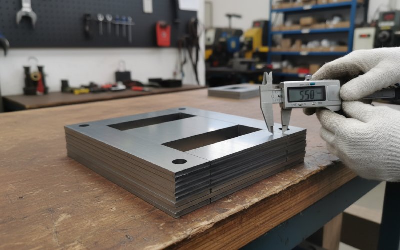
Lasciate che le pile di laminazione di Sino diano forza al vostro progetto!
Per velocizzare il progetto, è possibile etichettare le pile di laminazione con dettagli quali tolleranza, materiale, finitura superficiale, se è necessario o meno un isolamento ossidato, quantitàe altro ancora.
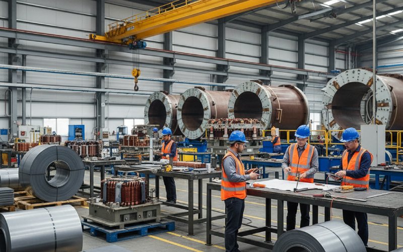
Cause principali della deriva delle prestazioni di laminazione CRGO nei lotti di produzione
Ordini Laminazioni CRGO con la stessa qualità, lo stesso rivestimento e lo stesso disegno. Tuttavia, la perdita a vuoto aumenta di 8%. La corrente di magnetizzazione supera il foglio di calcolo del progetto. Il rumore si sposta.
“Stessa specifica, risultato diverso”. Questo articolo parla di questo divario.
Indice dei contenuti
1. La specifica è fissa. Il processo non lo è.
Sulla carta, un lotto di laminazioni CRGO è definito da:
grado (ad es. M3, HI-B, raffinato in base al dominio, ecc.)
spessore nominale
rivestimento / classe di isolamento
perdita di nucleo e permeabilità di Epstein garantite
Ciò che è meno visibile è la dispersione all'interno La finestra di tolleranza della cartiera e il modo in cui le operazioni di taglio, impilatura e ricottura amplificano o smorzano la dispersione. Gli acciai a grana orientata sono altamente sensibili alla struttura; modeste variazioni nella chimica, nella struttura, nella dimensione dei grani e nelle tensioni interne producono cambiamenti misurabili nella perdita e nella permeabilità.
Quindi, due lotti che sono entrambi “conformi alle specifiche” possono produrre nuclei sensibilmente diversi una volta che sono stati perforati, impilati e bloccati. Questo è il nocciolo della deriva delle prestazioni.
Percorriamo la catena, dalla lastra alla pila di laminazione finita.
2. Variazione del lato mulino all'interno delle bobine “buone
2.1 Finestra chimica e sistema di inibitori
Anche all'interno di un grado, le cartiere regolano Si, Al, C, N e le specie inibitrici (MnS, AlN, ecc.) per guidare la ricristallizzazione secondaria e la struttura Goss. Piccole variazioni influenzano la distribuzione granulometrica e le proprietà magnetiche finali.
Lo vedi come:
Variazione da bobina a bobina nella perdita di Epstein, ancora all'interno della garanzia
Pendenze della curva B-H leggermente diverse
Sensibilità diversa in base alle condizioni di punzonatura e ricottura
Due bobine di calore diverso, con lo stesso grado nominale, non rispondono in modo identico alla stessa linea.
2.2 Struttura, granulometria e ingegneria del dominio
La nitidezza della struttura e la distribuzione granulometrica di Goss determinano la perdita e la permeabilità di base. La ricerca continua a dimostrare che piccoli cambiamenti nelle condizioni di ricristallizzazione, nella dispersione degli inibitori e nella temperatura di ricottura possono modificare il comportamento della struttura e della crescita dei grani, che poi si ripercuote direttamente sulla perdita del nucleo.
Non è possibile “aggiustare” completamente la situazione a valle, ma solo evitare di peggiorarla.
2.3 Variazione del rivestimento e della classe di isolamento
Le classi C della ASTM A976 (C-0...C-6) si differenziano per chimica, resistenza all'isolamento, attrito e comportamento di scarico delle sollecitazioni.
Si verificano due cose:
Risposta di taglio/punzonatura - I rivestimenti con attrito diverso modificano la tensione del nastro e la formazione di bave e rollover.
Comportamento dello stack - La resistenza dell'isolamento e lo spessore del rivestimento modificano il fattore di laminazione e la perdita interlaminare.
Se si cambia fornitore o classe di rivestimento “ma si mantiene tutto il resto”, la deriva dei lotti è quasi garantita.
3. Taglio: la qualità dei bordi è la prima variabile nascosta.
Quando il nastro lascia la taglierina, molte delle derive successive sono già state acquisite.
3.1 Altezza della fresa e deformazione del bordo
L'elevata bava e il forte ribaltamento non sono solo estetici. Sono:
ridurre il fattore di impilamento
creare microcorti tra le laminazioni
iniettare sollecitazioni locali proprio dove il flusso si affolla ai bordi
Ciò aumenta la perdita di corrente parassita localizzata e la perdita di isteresi e spesso si manifesta con una perdita maggiore e nuclei più rumorosi. L'esperienza del settore e gli studi sulla laminazione di motori e trasformatori collegano costantemente bave più elevate a perdite più elevate e a una minore efficienza.
Burr va alla deriva con:
affilatura e gioco dei coltelli
impostazione e tensione della linea di taglio
durezza del nastro e rivestimento (dalla sezione 2)
Quindi un lotto che è stato tagliato tardi nella curva di vita del coltello avrà tranquillamente prestazioni peggiori.
3.2 Diffusione della campanatura e della larghezza
La curvatura della striscia, l'onda del bordo e la variazione di larghezza sono solitamente “in tolleranza” fino a quando non si inizia a impilare e vedere:
Gli interstizi tra i gradini non si inseriscono in modo ripetibile
pressione di serraggio non uniforme
microspazi d'aria casuali all'interno delle pile
Tutto ciò si manifesta con una maggiore corrente di magnetizzazione e talvolta con una “misteriosa” deriva della perdita a vuoto.
3.3 Scelta della tecnologia di taglio
Quando i progetti si spostano verso spessori più sottili e geometrie più complesse, il processo di taglio stesso diventa una variabile importante. La tranciatura meccanica, l'intaglio, il taglio laser e le linee di taglio avanzate impongono diversi stati di stress e zone termicamente alterate sui bordi.
Un lotto tagliato su una vecchia linea di presse meccaniche e un altro su una più recente linea di taglio a misura può essere testato in modo diverso anche con bobine e disegni identici.
4. Punzonatura e intaglio: dal foglio alla laminazione
Ora la striscia diventa un pezzo. Ogni utensile e impostazione della pressa inizia a essere importante.
4.1 Usura dell'utensile e impostazioni della pressa
Come usura dei pugni:
L'altezza della bava aumenta
Il rollover peggiora
microfessurazioni sui bordi delle fessure
L'altezza di chiusura della pressa, lo spazio tra gli stampi, la lubrificazione e la velocità si spostano in base alle modifiche apportate alla produttività. Le variazioni quotidiane sono una delle ragioni più comuni della deriva delle prestazioni di laminazione nel mondo reale. Raramente compare nelle schede tecniche, ma è possibile vederla nelle foto al microscopio e nella perdita di anime.
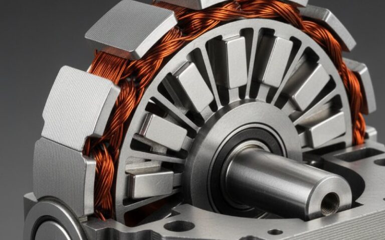
4.2 Errori di direzione dei grani e orientamenti misti
Il CRGO dipende dall'allineamento della direzione di laminazione con i percorsi di flusso principali. Un orientamento errato (anche un sottoinsieme di laminazioni ruotate di 90°) aumenta drasticamente la perdita locale e la corrente di magnetizzazione.
In produzione, questo può accadere quando:
Le bobine sono caricate al contrario su una linea
Gli strumenti di tranciatura sono condivisi tra i diversi pezzi e le diverse configurazioni.
gli operatori mescolano le parti “sinistra” e “destra” di due nidi diversi
Il lotto sembra a posto dal punto di vista visivo. Il banco di prova non è d'accordo.
4.3 Sollevatori di stress locali
Angoli interni acuminati, fori pilota troppo stretti e forti lavorazioni di formatura sono tutti elementi che concentrano le sollecitazioni. GOES è piuttosto sensibile; le sollecitazioni locali modificano la curva B-H e la magnetostrizione. Anche se il disegno è identico, le piccole regolazioni della pressa cambiano il grado di “lavorazione” dell'acciaio e quindi la perdita.
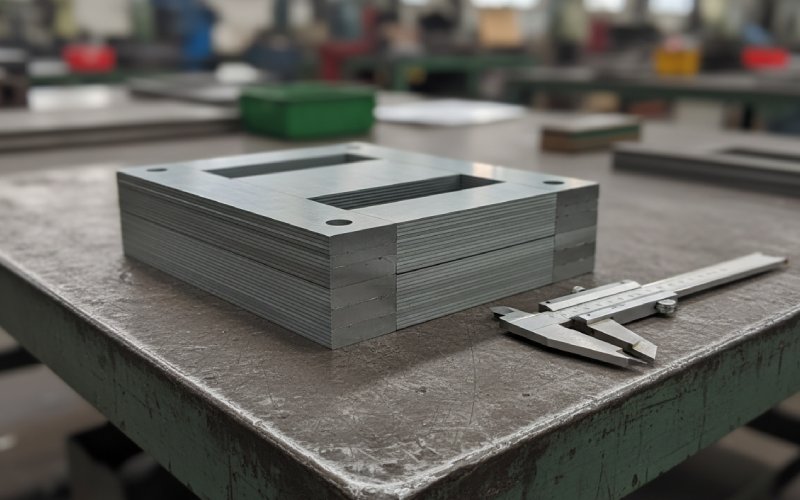
5. Accatastamento, geometria dei giunti e serraggio
È possibile rovinare buone laminazioni con un accatastamento approssimativo o rendere accettabile un materiale mediocre con un accatastamento disciplinato. Questo dato, da solo, dimostra quanto sia forte questo legame.
5.1 Deriva del fattore di laminazione
Le norme e i cataloghi delle cartiere parlano di fattore di laminazione (fattore di impilamento) per pile ordinate e idealizzate. Le pile reali, con bava e rivestimento, raramente corrispondono a questo valore.
Driver:
variazione dello spessore del rivestimento
Altezza della bava e deformazione del bordo
metodo di impilamento (manuale o robotizzato, coerenza dell'interleaving)
Se il modello CAD presuppone un ferro da 100% e il fattore di laminazione effettivo passa da 96% a 93%, la densità di flusso si sposta, così come la perdita e la corrente di magnetizzazione.
5.2 Accuratezza del giunto a T e del passo
La distribuzione delle perdite locali nei giunti a T e nelle sovrapposizioni dipende fortemente dall'angolo di sovrapposizione, dalla lunghezza e dal modello di strato. Gli studi dimostrano che la perdita localizzata del nucleo aumenta dai bordi esterni a quelli interni nelle giunzioni a T ad angolo misto quando l'allineamento è disattivato.
Fonti di deriva nella vita reale:
diversi team di assemblaggio che utilizzano abitudini di passo leggermente diverse
I dispositivi si usurano nel tempo, quindi le confezioni possono spostarsi.
nuovi progetti di anime che riutilizzano vecchi impianti di impilamento “sufficientemente vicini”.”
Alla fine si ottiene la stessa distinta materiali, ma un quadro di flusso locale diverso.
5.3 Pressione di serraggio e struttura del telaio
I nuclei sottocalibrati ronzano e si muovono. I nuclei sovraccaricati sono sottoposti a sollecitazioni meccaniche supplementari e possono presentare perdite più elevate. Un serraggio non uniforme crea prestazioni variabili a livello spaziale: alcune gambe si avvicinano alle specifiche, altre peggiorano.
La deriva del lotto appare quando:
modifiche alla sequenza di coppia
Il design del telaio è stato rivisto senza alcuna modifica dei limiti di prova.
I cuscinetti o l'isolamento sotto i gioghi si comprimono in modo diverso a causa del cambiamento di materiale.
6. Ricottura sotto sforzo: il moltiplicatore silenzioso
La ricottura sotto sforzo è una delle leve più potenti per le prestazioni dei CRGO, perché rilassa la lavorazione a freddo dovuta al taglio, alla punzonatura e all'impilamento. Molte schede tecniche danno per scontato che i nastri siano ricotti con distensione quando indicano i migliori valori di perdita.
La deriva si manifesta quando il processo reale si discosta:
il carico del forno diventa più denso nel tempo
Il tempo di immersione viene ridotto per ottenere una maggiore produttività.
Le termocoppie invecchiano, quindi la temperatura effettiva della laminazione cambia senza che nessuno se ne accorga.
dimensioni diverse del nucleo condividono lo stesso ciclo, anche se la massa termica non è la stessa
Risultato: un mese il processo allevia davvero lo stress, un altro mese lo fa solo a metà.
I test di base finiti rifletteranno questo aspetto.
C'è anche il sottile problema del “danneggiamento dopo la ricottura”:
saldatura o molatura in prossimità del nucleo
manipolazione e piegatura dei gioghi
pallinatura locale da infissi
Tutto ciò aggiunge nuovo stress dopo aver pagato il forno.
7. Manipolazione, stoccaggio e miscelazione dei materiali
Questa parte sembra banale. Non lo è.
7.1 Miscelazione di gradi o livelli di qualità
Alcuni mercati vedono l'importazione di materiali CRGO “secondi e difettosi”, che presentano un controllo meno rigoroso su planarità, bava, bombatura e proprietà. Gli operatori del settore hanno sottolineato come la bava e la curvatura dei bordi di questi materiali peggiorino direttamente il fattore di impilamento e le perdite di anime.
Se il vostro impianto di laminazione riempie occasionalmente questo tipo di materiale quando le scorte sono scarse, è inevitabile una deriva da un lotto all'altro, anche se la qualità di targa rimane la stessa.
ridurre la resistenza all'isolamento tra le laminazioni
danneggiare o scrostare i rivestimenti
introducono buchi di corrosione e rugosità della superficie
Tutto ciò si traduce in una maggiore perdita interlaminare e talvolta in un aumento del rumore.
7.3 Riutilizzo o rilavorazione delle laminazioni
La ribattitura, la riaffilatura o il riaccatastamento di lamiere provenienti da anime scartate o da serie di prototipi consente di risparmiare acciaio nel breve periodo e di creare incoerenza nel lungo periodo. Ogni fase di manipolazione aggiuntiva aggiunge stress, possibili graffi attraverso il rivestimento e dispersione della geometria.
8. Illusioni di misura e spec.
Gran parte di ciò che viene definito “deriva delle prestazioni” dipende dal modo in cui si confrontano i dati di test con quelli di produzione.
8.1 Test di Epstein vs realtà del nucleo costruito
Le garanzie del mulino si basano di solito sulle strisce di Epstein: ricottura con riduzione delle tensioni, orientamento ideale dei grani, percorso magnetico semplice.
Il vostro nucleo assemblato è:
punzonato
impilato con vera bava e rivestimento
bloccato in un telaio
a volte solo parzialmente alleviato dallo stress
Confrontando i risultati uno a uno si noterà sempre un divario. Ciò che conta è come questo divario cambia nel tempo.
Se il vostro processo aggiunge una “penalità” approssimativamente costante al risultato di Epstein, la deriva è bassa. Quando il vostro processo si disperde, la deriva è elevata. Molte aziende non tengono traccia di questo delta in modo esplicito, il che rende più lento il lavoro di root-cause.
8.2 Deriva del set-up di prova
Anche i laboratori più efficienti registrano variazioni:
calibrazione della densità di flusso
temperatura del nucleo durante i test a vuoto
posizionamento dei sensori e instradamento dei cavi
La perdita a vuoto è sensibile all'induzione, alla frequenza e alla temperatura, e la temperatura da sola può modificare sensibilmente la perdita in GOES.
Prima di dare la colpa alle laminazioni, vale la pena di verificare che il banco di prova, il suo cablaggio e il suo software non siano cambiati.
9. Riferimento rapido: sintomi tipici e probabili cause principali
Utilizzare questa tabella come filtro iniziale quando un lotto di pile di laminazione CRGO si comporta in modo diverso dal precedente.
Sintomo nei test di routine / FAT
Probabile causa cluster
Prima cosa da controllare velocemente
Soluzioni a medio termine
Perdita a vuoto +5-10% rispetto all'ultimo lotto, anche la corrente di magnetizzazione è più elevata
Aumento delle bave, riduzione delle sollecitazioni, diminuzione del fattore di laminazione
Misurare l'altezza della bava sul lotto attuale rispetto a quello precedente; controllare i dati di carico e di immersione del forno.
Inasprire i limiti di bava nell'OP; definire le corse massime dell'utensile per affilatura; qualificare le ricette del forno per dimensione del nucleo
Perdita a vuoto in aumento, corrente di magnetizzazione pressoché invariata
Perdita localizzata nei giunti, problemi di rivestimento/isolamento
Termografia sull'anima in esame; ricerca di giunzioni calde; verifica della classe di rivestimento o del cambio di fornitore
Standardizzare gli schemi a gradini e i dispositivi di impilamento; bloccare le specifiche di isolamento e i test in entrata.
Corrente di magnetizzazione in aumento, perdita solo leggermente in aumento
Variazione del fattore di laminazione, errori di orientamento dei grani, variazione del modello di serraggio
Pesare le pile rispetto a quelle teoriche; verificare i segni di direzione di rotolamento; controllare la storia della coppia di serraggio.
Specificare i test sul fattore di laminazione; aggiungere il poka-yoke per la direzione della grana sulla linea; riprogettare il telaio per una pressione più ripetibile.
Aumento del rumore con una modesta variazione della perdita
Distribuzione delle sollecitazioni, serraggio, ricottura parziale
Ascoltare il ronzio locale, ispezionare i punti di contatto del telaio; esaminare il registro del forno per quel lotto.
Migliorare il supporto e lo smorzamento dell'anima; mettere a punto il serraggio; rivedere le operazioni post-cottura (saldatura, rettifica).
Grande variazione tra le anime costruite dallo stesso lotto di laminazioni
Variazione dell'assemblaggio e dell'impilamento, deriva dell'impostazione del test
Confronto della geometria della pila, degli schemi di giunzione e dei registri di coppia; controllo incrociato del banco di prova con l'anima di riferimento
Standardizzare le istruzioni di lavoro; automatizzare o fissare una parte maggiore dell'impilamento; aggiungere controlli regolari di calibrazione del banco di prova.
10. Rendere più stabili le prestazioni di laminazione del CRGO
Non è possibile eliminare tutte le variazioni nell'acciaio elettrico a grana orientata. Ma si può progettare la fornitura di laminazione e la produzione di anime in modo che la maggior parte della variazione sia a monte e trasparente, non nascosta all'interno del proprio stabilimento.
Mosse tipiche che aiutano:
Specificare i limiti legati al processo, non solo il grado
Altezza massima della bava e metodo di misurazione
prove di accettazione del fattore di laminazione su pile campione
classi di rivestimento e fornitori consentiti
Traccia della genealogia bobina-core
sapere quale nucleo del trasformatore ha utilizzato quale bobina e quale configurazione di linea
quando un lotto va alla deriva, è possibile vedere se si raggruppa intorno a una bobina, a un utensile o a un carico di forno
Correlare la propria “firma del processo” con i dati del mulino
mantenere una piccola serie di anime di prova standard costruite nello stesso modo da ogni lotto di laminazioni
confronta la tua penalità con i numeri di Epstein del mulino nel corso del tempo
Trattare il taglio e la ricottura come parametri di progettazione, non solo come utilità di produzione.
quando i progetti si spostano su spessori più sottili o su obiettivi di perdita più stretti, occorre verificare se le linee e i forni esistenti sono ancora idonei
Se fatto sistematicamente, questo trasforma la “deriva del mistero” in un insieme di variabili controllate.
FAQ: domande comuni sulla deriva dei lotti di laminazione CRGO
1. Quale livello di variazione della perdita di anima tra i lotti di laminazione è realisticamente accettabile?
Non si otterrà mai uno spread pari a zero. Molti produttori di trasformatori considerano normale una variazione di ±3-5% nella perdita a vuoto tra i lotti (a condizioni di progetto e di prova costanti). Per ottenere risultati più stretti di così è necessario un taglio, una punzonatura e una ricottura molto controllati, oltre a una buona collaborazione con il mulino. Quando i risultati vanno al di là di questa fascia, è un segnale che invita a controllare gli utensili, il processo del forno e i registri dei materiali in entrata.
2. L'altezza della bava è davvero così importante se la resistenza dell'isolamento è elevata?
Sì. La bava è un indicatore della deformazione dei bordi e della distorsione della geometria locale, non solo dei cortocircuiti da giro a giro. Anche se l'isolamento è intatto, un'elevata bava aumenta la densità di flusso localizzata e introduce stress residuo, entrambi fattori che aumentano la perdita. Gli studi e l'esperienza del settore collegano livelli di bava più elevati a una maggiore perdita del nucleo e a un fattore di impilamento più scarso.
3. Posso “aggiustare” un lotto di laminazioni con perdite maggiori con una ricottura di distensione più lunga?
A volte si può ridurre la penalità, ma non si può cambiare la struttura e la chimica sottostante. Lo stress relief rimuove principalmente le sollecitazioni di lavorazione dovute al taglio e all'impilamento. Se la perdita più elevata è dovuta a differenze sul lato del mulino (dimensione dei grani, distribuzione degli inibitori, nitidezza della struttura), la ricottura non renderà il lotto identico a un coil migliore; renderà solo più coerente il vostro contributo.
4. Vale la pena specificare una perdita di Epstein più stretta rispetto al grado standard?
Può esserlo, ma solo se si controllano anche i processi interni. Le specifiche più rigide del mulino riducono la dispersione da bobina a bobina, il che aiuta. Se la vostra variazione dovuta a bava, impilamento e ricottura è maggiore della dispersione del mulino, difficilmente noterete il miglioramento. Il percorso abituale è: stabilizzare il processo interno → quindi negoziare tolleranze di laminazione più strette che si traducono effettivamente in una minore dispersione a livello di nucleo.
5. Con quale frequenza è necessario riqualificare gli utensili da taglio e i processi di impilamento per le laminazioni CRGO?
Pensate in termini di dati, non di calendario. Traccia: Altezza della fresa rispetto alle corse di ciascun utensile Perdita del nucleo in funzione dell'età dell'utensile e del carico del forno variazione tra gli operatori o turni di accatastamento Una volta individuato il punto in cui le prestazioni iniziano a degradarsi, si possono stabilire limiti di manutenzione preventiva o di riqualificazione appena prima di quel punto. Per molti impianti, questo limite è legato al numero di corse e alla curva di crescita delle bave misurate, anziché “ogni X mesi”, perché il volume di produzione e il mix di materiali variano.
Cheney è un ingegnere applicativo senior di Sino, con una forte passione per la produzione di precisione. Ha una formazione in ingegneria meccanica e possiede una vasta esperienza pratica nella produzione. Alla Sino, Cheney si concentra sull'ottimizzazione dei processi di produzione delle pile di laminazione e sull'applicazione di tecniche innovative per ottenere prodotti di alta qualità.
Opuscolo sui nuovi prodotti
Inserite il vostro indirizzo e-mail e vi invieremo l'ultima brochure!
Lasciate che le pile di laminazione di Sino diano forza al vostro progetto!
Per velocizzare il progetto, è possibile etichettare le pile di laminazione con dettagli quali tolleranza, materiale, finitura superficiale, se è necessario o meno un isolamento ossidato, quantitàe altro ancora.