Lasciate che le pile di laminazione di Sino diano forza al vostro progetto!
Per velocizzare il progetto, è possibile etichettare le pile di laminazione con dettagli quali tolleranza, materiale, finitura superficiale, se è necessario o meno un isolamento ossidato, quantitàe altro ancora.
Progettazione di motori BLDC a rotore esterno: Guida facile alla modellazione dei motori elettrici
Un motore CC brushless a rotore esterno è un tipo di motore elettrico robusto. In questo tipo di motore, i magneti sul rotore girano sul all'esterno degli avvolgimenti dello statore. Questo conferisce loro capacità speciali, come una coppia elevata. Questo articolo è per voi. Vi aiuterà a capire come progettare un motore CC brushless a rotore esterno migliore. Vi mostreremo come la modellazione al computer possa semplificare le fasi di progettazione del motore e aiutarvi ad avere successo. Imparerete i passi principali per migliorare il vostro motore elettrico BLDC in modo che funzioni al meglio.
Indice dei contenuti
Che cos'è un motore BLDC a rotore esterno?
Il motore brushless a corrente continua (motore BLDC) è un tipo comune di motore elettrico. Piace perché funziona bene e si può contare su di esso. La maggior parte dei motori che si vedono ha il rotore che gira all'interno dello statore. Si tratta di una struttura a rotore interno.
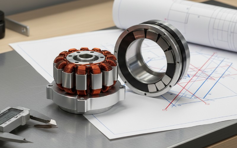
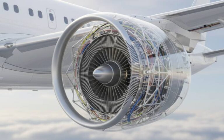
Un motore CC brushless a rotore esterno è diverso. Il rotore è dotato di magneti permanenti e si trova all'esterno. Lo statore e le sue bobine di avvolgimento si trovano all'interno. Questo design del motore significa che il rotore è più largo. Questo cambiamento è un grande vantaggio per il motore BLDC a rotore esterno. Gli conferisce una coppia elevata. La forza magnetica spinge il motore lontano dal centro. Ciò rende la forza di rotazione, chiamata coppia, molto più forte. Ciò rende questo motore BLDC ideale per applicazioni quali droni, biciclette elettriche e ventilatori.
Perché una buona modellazione è il primo passo per la progettazione del motore?
Prima di costruire un motore BLDC vero e proprio è necessario un progetto. Nella progettazione dei motori, questo piano è un modello al computer. Modellare significa creare una copia del motore CC senza spazzole sul computer. Si tratta di un passo molto importante.
Un buon modellismo aiuta a risparmiare molto tempo e denaro. Non è necessario costruire molti motori di prova reali. Si possono invece provare centinaia di idee progettuali al computer. La modellazione vi permette di vedere come funzionerà il vostro motore BLDC prima ancora di costruirne uno. Potete vedere quanto è forte, trovare i suoi punti deboli e migliorare ulteriormente le sue parti migliori. Un buon modello di motore è il punto di partenza per un'ottima progettazione. Senza un buon modello, si tirano solo delle ipotesi. Con una buona modellazione, si può essere certi che il progetto e le prestazioni soddisfino gli obiettivi prefissati. Ecco perché tutte le nuove macchine elettriche sono realizzate con questo tipo di modellazione intelligente.
Quali sono le parti principali da modellare?
Quando si inizia a modellare il motore BLDC, è necessario impostare le sue parti principali. Queste parti sono chiamate parametri di progettazione. Ogni parametro modifica la coppia finale del motore e il suo funzionamento. È molto importante che questi parametri siano corretti per un buon progetto del motore.
Ecco alcuni dei parametri di progettazione più importanti da inserire nella modellazione:
Parametro
Cosa fa
Perché è importante per la modellazione
Numero di pali
Il numero di coppie di magneti sul rotore.
Modifica la velocità e la coppia del motore. Un numero maggiore di poli significa spesso una coppia maggiore, ma una velocità nominale inferiore.
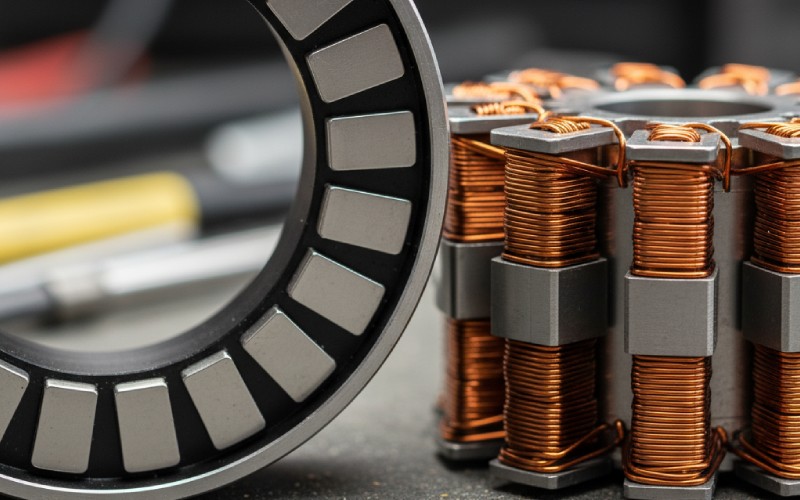
Spessore del magnete
Lo spessore dei magneti permanenti.
Una parte principale che determina l'intensità del campo magnetico. I magneti più spessi forniscono una coppia maggiore, ma costano anche di più.
Traferro
Il piccolo spazio tra lo statore e il rotore.
Un traferro più piccolo rende la forza magnetica più forte. Ma è più difficile da realizzare. La modellazione aiuta a trovare la dimensione migliore.
Modello di avvolgimento
Come sono avvolti i fili sullo statore.
Questa parte modifica la velocità, la coppia e la tensione necessaria al motore.
Il progetto del motore deve trovare un buon mix di queste variabili. Ad esempio, un magnete di spessore maggiore può fornire una coppia maggiore, ma potrebbe rendere il motore bldc troppo pesante. La modellazione aiuta a trovare il progetto ottimale per le proprie esigenze.
Come funziona la modellazione con il metodo degli elementi finiti (FEM)?
Come può un computer comprendere un motore BLDC con così tante parti? La risposta è il metodo degli elementi finiti (FEM). Si tratta di un potente strumento di modellazione. Il FEM taglia il progetto del motore in migliaia di piccoli pezzi. Questi pezzi sono chiamati "elementi finiti". Utilizza quindi la matematica per capire come si comportano i campi magnetici in ogni piccolo pezzo.
Calcolando questo dato per tutti i bit, il software FEM può fornire un'immagine molto chiara dell'intero motore bldc. Può mostrare la densità del flusso magnetico in ogni area dello statore e del rotore. Il metodo degli elementi finiti è il modo migliore per vedere come funzionerà il vostro motore CC senza spazzole. Questa verifica approfondita è molto più efficace delle semplici regole matematiche. È infatti in grado di comprendere forme complesse e il comportamento dei materiali. L'uso del FEM è un passo importante per ottimizzare il progetto del motore.
È possibile utilizzare Ansys per la modellazione dei motori BLDC?
Sì, è possibile. Ansys è uno strumento software molto comune e potente per la modellazione FEM. Molti ingegneri utilizzano Ansys per progettare e testare macchine elettriche. Tra queste c'è anche il motore CC senza spazzole a rotore esterno. Ansys consente di costruire un modello completo al computer del motore BLDC. È possibile impostare ogni parametro, dal tipo di magnete ai dettagli dell'avvolgimento.
Dopo aver costruito il modello di motore in Ansys, è possibile eseguire dei test sul computer. Questi test sono come una prova al computer. Il software mostra la coppia erogata dal motore bldc, la sua potenza di uscita e il suo funzionamento. I risultati della simulazione di Ansys sono risultati di cui ci si può fidare. Vi aiutano a fare scelte intelligenti per migliorare il progetto del vostro motore. Ansys è un ottimo strumento per qualsiasi motore serio per veicoli elettrici o altri usi. La potenza di modellazione FEM di Ansys è di altissimo livello.
Come scegliere i materiali giusti per la modellazione?
I materiali scelti per il motore BLDC sono importanti. I materiali giusti garantiscono un'elevata efficienza e migliori prestazioni del motore. La modellazione FEM deve contenere informazioni su questi materiali. La cosa più importante di un materiale per un motore BLDC è il suo comportamento magnetico, ovvero come si comporta con i magneti.
Per il rotore si utilizzano magneti permanenti. Il tipo di magnete, come il neodimio (NdFeB), fa una grande differenza. Per lo statore si utilizzerà un acciaio speciale. Il modo in cui questo acciaio agisce è mostrato da una cosa chiamata curva B-H. La curva B-H indica al software di modellazione come si comporta il materiale in un campo magnetico. È importante che i magneti siano magnetizzati fino al punto di saturazione. La curva B-H mostra questo punto in un circuito chiuso. Questa modellazione dettagliata aiuta a indovinare le perdite di ferro. Inoltre, assicura che il motore bldc funzioni come si pensa. L'uso della curva B-H corretta nella modellazione FEM è molto, molto importante per ottenere risultati di simulazione veritieri.
Come migliorare il progetto per ottenere la massima coppia?
Uno dei motivi migliori per utilizzare un motore CC brushless a rotore esterno è ottenere una coppia elevata. Pertanto, un obiettivo comune è quello di ottenere la coppia massima possibile dal progetto del motore. La modellazione è il modo in cui si ottiene questo risultato. Per ottenere la coppia massima, è necessario testare diverse variabili di progetto.
Utilizzando il software di modellazione FEM, è possibile eseguire dei test. Questi test mostrano come la variazione di ciascun parametro modifica la coppia.
E se si aumenta lo spessore del magnete? La modellazione potrebbe mostrare un salto di coppia di 10%.
E se si riduce il traferro? La verifica FEM mostrerà un'attrazione magnetica più forte e una coppia maggiore.
E se si cambia il numero di poli? I risultati della simulazione indicheranno la nuova coppia a una diversa velocità nominale.
È possibile eseguire centinaia di test al computer. Questo processo di prova e modifica si chiama ottimizzazione del progetto. Consente di trovare la migliore combinazione di parametri di progettazione per ottenere la coppia massima dal motore BLDC. Questo è molto utile per applicazioni come i veicoli elettrici, dove è necessaria una coppia elevata.
Qual è l'obiettivo dell'ottimizzazione del progetto per un'elevata efficienza?
Ottenere la coppia massima è ottimo. Ma non è l'unico obiettivo. È necessario che il motore brushless a corrente continua abbia anche un'elevata efficienza. Un motore ad alta efficienza utilizza bene l'energia elettrica. La trasforma in potenza utile in uscita. Spreca meno energia sotto forma di calore. Si tratta di un aspetto molto importante per gli oggetti che utilizzano le batterie, come i droni o le auto elettriche.
Per ottenere un'efficienza maggiore, è necessario ridurre le perdite nel motore bldc. I due tipi principali di perdite sono le perdite di rame (nell'avvolgimento) e le perdite di ferro (nello statore). La modellazione FEM è in grado di ipotizzare entrambi i tipi di perdite. L'ottimizzazione del progetto per l'efficienza potrebbe comportare l'adozione di questi accorgimenti:
Cambiare l'avvolgimento per utilizzare un filo più spesso, che riduce la perdita di rame.
Scegliere un tipo di acciaio migliore con una curva B-H migliore per ridurre le perdite di ferro.
Trovare il design ottimale che fornisca una buona quantità di coppia e che abbia anche un'elevata efficienza.
A volte, il tentativo di ottenere la coppia massima può portare a una minore efficienza. È qui che l'ottimizzazione multi-obiettivo può essere d'aiuto. Questo strumento di modellazione intelligente aiuta a trovare un progetto di motore che abbia una coppia elevata e che funzioni molto bene. Trova i valori ottimali per le vostre esigenze.
Come si studiano i risultati dei test di modellazione?
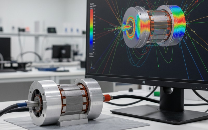
Dopo che il software di modellazione FEM esegue un test, fornisce molti dati. Questi sono i risultati della simulazione. È molto importante sapere come leggere questi risultati per migliorare la progettazione del motore. I risultati dell'analisi vengono spesso visualizzati sotto forma di grafici e mappe a colori.
Ad esempio, una mappa a colori del motore BLDC può mostrare la densità del flusso magnetico. È possibile individuare i punti in cui il campo magnetico è troppo debole o troppo forte. Un grafico può mostrare la coppia del motore mentre gira. Si può verificare se la coppia è costante o se sale e scende. Osservando i risultati di queste analisi, è possibile individuare i problemi. Forse la forma dello statore causa perdite di ferro supplementari. O forse lo spessore del magnete non è sufficiente per raggiungere la velocità e la coppia nominali. I risultati della simulazione mostrano cosa fare per ottimizzare il motore bldc. Ricordate, come si dice in documenti come il atti della conferenza internazionale 2019 sulle macchine e i sistemi elettriciLe opinioni e i dati contenuti in tutte le pubblicazioni sono spesso di un solo autore. Ciò significa che è necessario essere in grado di comprendere da soli i dati della modellazione FEM.
Quali sono le ultime fasi della verifica della progettazione e del lavoro?
Avete costruito un modello. Avete eseguito dei test al computer. Avete esaminato i risultati e apportato modifiche. La modellazione mostra che ora avete un ottimo progetto di motore con un'elevata potenza di uscita. Qual è il prossimo passo? L'ultima fase consiste nel verificare il funzionamento complessivo del motore. Si tratta delle prestazioni del motore. Dovreste avere un progetto finale del motore che soddisfa tutti i vostri obiettivi.
È qui che si effettua un'ultima verifica del progetto ottimale. La modellazione deve garantire che sia stato raggiunto l'obiettivo di massima efficienza e coppia. È anche una buona idea verificare come il motore elettrico bldc funzionerà in altre situazioni. Cosa succede se si riscalda? La modellazione può aiutare a indovinarlo. Molti documenti, come il atti della conferenza internazionale sulle macchine e i sistemi elettrici 2018, mostrano diverse idee di design. È importante sapere che i dati contenuti in tutte le pubblicazioni provengono solo da quei ricercatori. La modellazione FEM e lo studio da parte vostra sono ciò che dimostra che il vostro progetto è buono e pronto. Quest'ultimo controllo tramite la modellazione assicura che le prestazioni dei motori BLDC saranno eccellenti quando si costruirà finalmente un motore reale e funzionante.
Cose fondamentali da ricordare
Un motore BLDC a rotore esterno offre una coppia elevata perché il rotore si trova all'esterno.
La modellazione è il primo grande passo. Consente di risparmiare tempo e denaro perché prima è possibile testare il motore bldc su un computer.
Il metodo degli elementi finiti (FEM) è un potente strumento di modellazione che fornisce risultati molto veritieri sui campi magnetici del motore bldc.
Software come Ansys aiutano a costruire un modello di motore e a eseguire test per verificarne le prestazioni.
L'ottimizzazione del progetto è il modo in cui si modificano i parametri di progetto (come lo spessore del magnete o il traferro) per migliorare il motore bldc.
Gli obiettivi principali sono di solito quelli di ottenere la massima coppia e un'elevata efficienza riducendo le perdite.
L'esame dei risultati della simulazione mostra come migliorare il progetto del motore per creare il miglior motore CC senza spazzole.
Condividi il tuo amore
Charlie
Cheney è un ingegnere applicativo senior di Sino, con una forte passione per la produzione di precisione. Ha una formazione in ingegneria meccanica e possiede una vasta esperienza pratica nella produzione. Alla Sino, Cheney si concentra sull'ottimizzazione dei processi di produzione delle pile di laminazione e sull'applicazione di tecniche innovative per ottenere prodotti di alta qualità.
Opuscolo sui nuovi prodotti
Inserite il vostro indirizzo e-mail e vi invieremo l'ultima brochure!
Lasciate che le pile di laminazione di Sino diano forza al vostro progetto!
Per velocizzare il progetto, è possibile etichettare le pile di laminazione con dettagli quali tolleranza, materiale, finitura superficiale, se è necessario o meno un isolamento ossidato, quantitàe altro ancora.