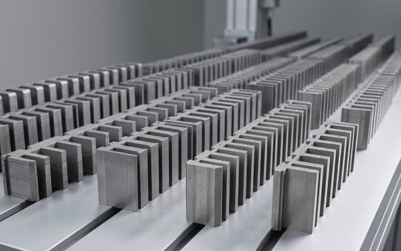
Sinoのラミネーションスタックにお任せください!
プロジェクトをスピードアップするために、ラミネーションスタックに以下のような詳細なラベルを付けることができます。 寛容, 材料, 表面仕上げ, 酸化絶縁が必要かどうか, 数量などなど。

紙の上では、「幅:0-230 mm、+0.00 / -0.20 mm」は無害に見える。公差表の別の行に過ぎない。.
ショップの現場では、その同じラインが勝負の分かれ目となる:
CRGOのグレードと厚みが最も注目されています。しかし、すでに低損失グレードを購入されている場合、サプライヤーのスリット方法と管理方法は、CRGOのグレードと厚さに大きく影響します。 ラミネート 幅は、製造品質と無負荷ロスを顕著に動かすレバーの1つである。サプライヤー自身、差別化の核となる要素として、タイトな幅のコントロールと低バリを強調している。.
この記事では、その細い鋼鉄の帯にとどまる: CRGOラミネーションのスリット幅公差. .コイルからラミネーションスタックへ、エアギャップへ、そして最終的にワットロスや着磁電流へと、どのように移動するのか。.
形式的な定義はすでにご存知だろう。.
一般的な規格に基づく典型的なラミネーション公差表では、次のように規定されている:
また、CRGO原料のスリットコイル製造業者では、コイル幅の公差がもっと緩い場合もある(例えば、コイル幅で0~+2mm)。.
つまり、チェーンに3つの異なる「幅の現実」があることになる:
図面では通常、(3)についてしか触れていない。(1)と(2)がどれだけスタックに漏れるかは、サプライヤーの工程能力によって決まります。.

幅の許容範囲は手足を縮めたり広げたりするだけではない。重要な3つの場所に漏れるのだ:
四肢のラミネーションが公差の下限に向かってふらつき、ヨークのラミネーションが公差に近くなると、ステップ・ラップ・ジョイントがきれいに並ばなくなる。こうなると
ラミネーションの品質に関するいくつかのテクニカル・ノートでは、寸法誤差(幅、角度、キャンバー)が不要なエアギャップを生み、無負荷損失がシングルシート試験で予測される以上に高くなることを明確に警告している。.
きつくクランプしても、実際のコアはわずかに弾性のあるシステムです。片方のサイド・リムがわずかに狭いラミネーションで作られている場合、次のようになる:
これは組み立てにかかる時間だけではない。その場しのぎの修正は、コアのクランプの仕方や応力のかけ方を変えてしまうことが多く、それがロスに跳ね返ってくるのだ。.
多段階重ね継ぎでは、ラミネーションパケット間の幅の違いにより、各段階での重なりが変化します。スムーズな磁路の代わりに、次のようなことが起こる:
優れたステップ・ラップ設計は、ストリップ幅が一定であることを前提としている。幅がコイルに沿ってずれるほど、実際のジョイントは設計でシミュレーションしたものからずれることになる。.
エンジニアは「-0.2mm幅」が磁束密度を劇的に押し上げるのではないかと心配することがある。生の面積の影響は通常小さい。.
単純なケースを考えてみよう:
面積は幅に比例する:
δa / a ≈ -0.2 / 250 = -0.08%
磁束密度は、固定ボルトと固定巻数で同じ0.08%だけ上昇します。1.7T付近のコア損失がB^1.6とほぼ等しいとすると、それは約0.08%にしかならない。 0.13%以上の損失 幅の変化だけから。.
だから 幅公差による純粋な断面変化は大悪人ではない.
悪役は以下の通り:
これらは単純なΔB計算では把握できないが、組立てコア損失がシングルシート試験損失を上回る理由として何度も繰り返し指摘されている。.
もっと物理的な方法で、このチェーンの中を歩いてみよう。.
許容範囲外の幅と相互作用する:
ヨークの幅がわずかに広いと、その段差がリムスタックからはみ出る。そうすると ローカル・セパレーション クランピングは、いくつかのラミネーションを他のラミネーションより強く押しつぶさなければ、完全に閉じることができない。.
小さな隙間でも局所的なリラクタン スを大幅に上昇させます。CRGOの取り扱いに関するテクニカルノートによれば、接合部の不十分なカット角や形状のばらつきは、主にこうした余分な隙間や歪んだ磁束経路によって、コア全体の損失をシート本来の損失よりも数パーセント上昇させる可能性があります。.
幅トレランスは、そのシーンにおける静かな共犯者である。.
幅のドリフトによってスタックがわずかにくさび状になると、クランピングビームが各ラミネーションに均等に荷重をかけない:
圧力が高すぎると絶縁皮膜が局部的に損傷し、層間電流や余分な渦損失が発生する可能性があり、圧力が低すぎるとエアポケットが残る。同じCRGOのガイダンス・ドキュメントでは、過度のクランプ圧力と表面汚染について、それ以外は良好な素材における実際の損失増加要因として述べている。.
幅の変化は、ストレスのホットスポットとコールドスポットを無意識のうちに作り出す方法のひとつだ。.
スリットは幅の問題だけではない。この工程では残留応力も発生し、ストリップエッジが圧延方向と平行でない場合、有効結晶粒方向がわずかに乱れることがある。.
幅のコントロールが悪いと、その傾向が見られる:
つまり、実用的なバンドルというわけだ: 幅のコントロールが悪いと、通常、局所的な磁気特性が予測しにくくなる。, たとえ平均的なコイルがP1.7/50の制限を満たしていたとしても。.
さて、誰もが先延ばしにしている部分、それは実際に何を指定するかということだ。.
以下はその一例である。 実際的見解 これは、一般的な公差表と、製造やロスに起こりがちなことを融合させたものである。数値は例示であるが、広く公表されているラミネーション公差データに基づいている。.
| ラミネート幅(mm) | 図面上の典型的な「標準」公差 | より厳しい練習が要求される | コアビルドにおける通常の意味 | ジオメトリーによる典型的な損失影響(定性的) |
|---|---|---|---|---|
| 0-100 | +0.00 / -0.15 | ±0.05から±0.10 | 小型部品(シャント、小型EIコア)。主なリスクは、異なるコイルのストリップを混ぜること。. | ジオメトリーの問題は、アングルやキャンバーも悪い場合にのみ支配的になる。. |
| 100-230 | +0.00 / -0.20 | ±0.05から±0.10 | 配電変圧器のLVリムやヨークによく見られる。幅のドリフトは、異なるスリットのコイルが混在すると、目に見える段差の不一致として現れ始める。. | ギャップやクランプの仕方によって、“良い ”ビルドと “雑な ”ビルドの間に数パーセントのロスが生じる。. |
| 230-400 | +0.00 / -0.30 | ±0.10 | より大きなリム/ヨークに使用。長いステップでは、リム/ヨークのパケット間に0.3mmの差があっても、顕著なオーバーハングが生じる。. | ここでの幅のコントロールの悪さは、純粋な損失と同様に、高い着磁電流とノイズとして現れる。. |
| 400-750 | +0.00 / -0.50 | ±0.10~±0.20(ハイエンドサプライヤーによるもののみ) | 大きなパワーコア、長いステップ長、重いスタック。幅のコントロールが緩いと、組み立てに時間がかかり、シミングや、時には図面の変更も必要になる。. | ロスの広がりは、同じ原料バッチのベストスタックとワーストスタックの間で数パーセントになることもある。. |
注釈
デザインへのメッセージ 太い手足と長いステップは、幅のコントロールが緩むことによるダメージを増幅させる。, 面積の変化が大きいからではなく、ジオメトリーエラーが蓄積されるからだ。.
購買部門がフラックス密度を選ぶことはほとんどないが、サプライヤーと公差言語は絶対に選ぶ。.
デザインファイルに触れずにできることは以下の通りです。.
RFQ / PO文書の中で:
サプライヤーによっては、積極的な選別とスクラップによってのみラミネーションの許容範囲を満たすところもある。.
検査報告書に「幅OK」と一行で書くのではなく、要求する:
すべての出荷に完全なSPCチャートは必要ない。幅が管理されているか、あるいは単に「検査」されているかを明らかにするには、四半期ごとまたはPPAPスタイルの調査で十分です。.
幅の許容範囲は、それ自体では役に立たない:
購買担当者は、関連性のない4つの箇条書きではなく、これらを1つのまとまりとして扱うべきである。.
エンジニアリングの観点からは、3つのノブがある:
これまで見てきたように、300mmのリム幅で最悪-0.3mmでも0.1%の面積変化である。これだけでは、無負荷損失に対する5-10%の設計マージンを正当化することはできない。.
だから、Bをその場しのぎで大きく膨らませるのではなく、次のようにするのが現実的だ:
シングルシートのテストデータはお世辞にも良いとは言えない。実際のコアは次のような問題を抱えている:
目標とするコア・ロスを選ぶとき:
幅公差コントロールは、その「加算器」を引き締める1つのレバーである。.
公差を厳しくすると、どこかでコストがかかる(スクラップ、スリットの遅さ、より良いナイフ、チェックの回数)。通常、公差を厳しくする価値はある:
コアが既存の損失保証に遠く及ばない場合、幅公差が最初に修正すべきボトルネックになることはほとんどありません。等級、厚さ、バリ、組み立て工程から始めましょう。.
計測ラボは必要ない。基本的なルーチン:
幅、バリ、キャンバー、厚みといったパラメータが各機械でモニターされていると公言しているサプライヤーもいくつかある。.
もしサプライヤーがそのデータの共有を拒否すれば、それは独自の測定方法となる。.
のリム幅とヨーク幅の場合。 100-300 mm 一般的なラミネーション・チャートでは
最大幅230mmまで、+0.00 / -0.20 mm、,
最大400mmまで+0.00 / -0.30 mm。.
標準的な配給設計であれば、これで十分だ もし バリ、キャンバー、角度もコントロールされる。ロスやノイズの保証が厳しい場合は 対称 ±0.10 mm クリティカル幅に関する(能力を証明する)アップグレードは妥当である。.
必ずしもそうではない。あるポイント以下では、主な損失とノイズの要因になる:
CRGOグレードそのもの、,
ラミネーションの厚さ、,
ジョイントの設計と組み立ての品質。.
もしあなたのコアが定期的に10%以上の損失目標を逃しているなら、幅が最初に厳しくなることはないだろう。幅の許容差を 微調整ツール 基本的なことがコントロールできれば.
なぜなら オーバーサイズ ラミネーションは直ちに機械的な問題を引き起こす:
コイルの挿入が難しい、,
フレームとクランププレートとのミスアライメント、,
組み立て時に無理に曲げられる危険性が高まる。.
少しくらいサイズが小さくても我慢しやすい(磁束密度にわずかなペナルティを支払うことになり、シミングの回数が増えるかもしれない)ので、多くのラミネーション公差表では、公称幅からマイナスの偏差しか許容していない。.
少なくなったが、消えることはない。.
巻芯用:
ストリップ幅は通常、コア全体で一定である、,
同じ意味でのマイター・ジョイントはない、,
ビルドは、小さな幅の偏差よりも、エッジの品質や内部応力に敏感である。.
つまり、幅のコントロールの主な役割は以下の通りだ:
巻芯が設計された窓とフレームに合っていることを確認する、,
カットポイントや継ぎ目での「階段」効果を避ける、,
応力分布を均一に保つ。.
たまにね。.
もし、あなたの損失が小幅なもの(数パーセント)であり、その時期と重なるのであれば:
新しいラミネーション・サプライヤー、,
関節の接触が悪くなる、,
コアビルドをさらに手直しする、,
そうであれば、スリット幅のコントロールは、エアギャップやストレスを介して、原因の一部である可能性がある。.
損失のジャンプが大きい場合(10-20%)、最初に見てください:
グレードや厚みが静かに変化しても、,
クランプのやり方が変わったのか、アニーリングが変わったのか、,
ラミネーションが取り扱い中に破損したり汚染されたりしたかどうか。.
幅の許容差だけで非常に大きなジャンプが説明できることはほとんどない。.
監査済みの安定したサプライヤー
初回承認時に一度だけ、,
では 毎年 あるいは、スリット設備、工具、工程ルートを変更するたびに。.
工場での継続的な受入検査と組み合わせることで、正式な調査の合間に漂流物をキャッチすることができる。.