Let Sino's Lamination Stacks Empower Your Project!
To speed up your project, you can label Lamination Stacks with details such as tolerance, material, surface finish, whether or not oxidized insulation is required, quantity, and more.

Power transformers are the big, quiet workhorses of our electrical world. They take voltage up or down so we can move power from where it’s made to where we use it. But a transformer is only good if it’s efficient and safe. A problem in a single power transformer can cause big trouble for our power systems. That’s why transformer testing is so important. In this article, I’m going to share the four main tests to check a power transformer. This isn’t just for a big engineer. It’s for anyone who wants to understand how we keep our power flowing. We will look at what these tests do and what they tell us about the health and efficiency of a transformer.
When a power transformer fails, it’s not pretty. That’s why we don’t just put a new transformer into service and hope for the best. We test it. We test it a lot. Transformer testing is a set of checks we do to make sure a power transformer is working right. The main goal is to prevent a fault. A fault can cause power outages and damage equipment. Good testing helps us find a small defect before it becomes a big problem. This makes the whole electrical system safer and more reliable.
The efficiency of a transformer is a big deal. An inefficient transformer wastes electricity by turning it into heat. This wasted energy costs money. Over the life of a big power transformer, that can be a lot of money. The tests we conduct help us calculate the efficiency of the transformer. By checking its performance, we can be sure it meets the specification it was built to. Every test gives us a piece of the puzzle about the transformer’s health. It’s a key step when we commission a new transformer or do maintenance on an old one. This is a vital part of power transmission.
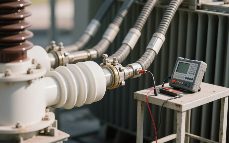
One of the first tests we do is the winding resistance test. This may sound complex, but the idea is simple. Every transformer has coils of wire inside it called a winding. We have a primary winding and a secondary winding. Electrical current flows through this winding. These wires have a very low electrical resistance. We need to measure this resistance to make sure it’s correct.
To do this measurement, an engineer will use a special tool. We pass a small, safe DC current through each winding of the transformer. The tool then measures the voltage drop across that same winding. Using Ohm’s law (Resistance = Voltage / Current), the tool can calculate the winding resistance very precisely. We perform this test on every winding and at every tap changer position. A tap changer lets us make small changes to the voltage ratio of the transformer. Each tap has its own connection, and we need to test them all. A transformer has many connections that we test.
So why do we measure the resistance? A correct winding resistance measurement tells us a lot. First, it tells us that the winding is not broken. If the wire was cut, the resistance would be infinite, and no DC current would flow. This simple test confirms the electrical circuit is complete. More importantly, this test helps us find bad connections. I’ve seen cases where a bolt on a terminal was not tight enough. This creates high resistance, which causes excessive heat. That heat can damage the transformer’s insulation.
The winding resistance test can detect problems inside the winding of the transformer that you can’t see. For example, if some of the wires in a winding were damaged during manufacturing, the resistance might be higher than expected. By comparing the measured value to the value from the factory test report, we can spot a problem. For three-phase transformers, we also compare the resistance of the winding in each phase. The numbers should be very close. If one phase has a much higher resistance, it’s a red flag for a potential defect in that transformer winding. It’s a simple but powerful test.
Next up is the turns ratio test, or TTR test. This is another fundamental test for any transformer. A transformer works by having a different number of turns of wire on its primary and secondary winding. The ratio of these turns sets the voltage ratio. For example, if the primary winding has 100 turns and the secondary winding has 10 turns, the turns ratio is 10 to 1. If you put 100 volts AC into the primary, you’ll get 10 volts AC out of the secondary.
The turns ratio test checks this exactly. We use a special instrument called a turns ratio tester. The engineer will connect the instrument to the high voltage and low voltage winding of the power transformer. The test set applies a low, safe AC voltage to one winding and carefully measures the voltage it gets on the other winding. From this measurement, it can calculate the exact turns ratio. We run this test for every tap position because each tap changes the number of turns in the circuit. This test checks the core function of the transformer.
The main reason to run a turns ratio test is to verify that the transformer will produce the correct output voltage. If the ratio is wrong, the voltage levels in the power system will be wrong. This can cause all sorts of problems for the equipment connected to it. This test is a great way to detect a manufacturing error or shipping damage. A serious mechanical shock can cause the winding to move or get shorted.
A short-circuit between turns in a winding is a very serious fault. It means the current is taking a shortcut, skipping some of the turns. This would change the turns ratio. The turns ratio test is very sensitive and can detect even a short-circuit in a single turn. Finding this early can prevent a catastrophic failure of the transformer later. We compare the measured ratio for each phase and each tap with the nameplate values. Following international standards like IEC, the measured value must be very close to the expected value, usually within 0.5%. It is a vital integrity test for the transformer.
A power transformer has a lot of high voltage inside. We need to make sure that voltage stays where it belongs. This is the job of the transformer’s insulation system. The insulation is usually special paper and oil that surrounds the winding. It prevents the high voltage from jumping to another winding or to the grounded metal tank of the transformer. If the insulation fails, you get a short-circuit, and that’s a very bad day.
The insulation resistance test checks the quality of this insulation. Good insulation has a very high electrical resistance. Bad insulation, perhaps due to moisture or aging, will have a lower resistance. This test helps us see how good the insulation is. We measure the insulation resistance between the different windings and between each winding and the ground. This test gives us a picture of the health of the entire insulation system of the transformer. It is one of the most important safety and reliability tests we perform on a transformer.
To conduct an insulation resistance test, an engineer uses a tool often called a Megger. This tool applies a specific DC voltage, like 1000 or 5000 volts, to the insulation for a set time, often for 1 minute. The voltage is high enough to test the insulation but not high enough to damage a healthy transformer. While the voltage is applied, the instrument will measure the small amount of current that flows. This flow of current is called leakage current.
Using this measured current, the tool calculates the insulation resistance. A high resistance value (in the millions or billions of ohms) is good. It means the insulation is clean, dry, and doing its job. A low insulation resistance reading is a warning sign. It often means moisture has gotten into the transformer oil and paper, which is a major problem that can lead to failure. We record this value and track it over time. If we see the resistance going down at each maintenance test, we know the transformer insulation is getting older and may need attention. This test helps to prevent a fault in the power transformer.
Now let’s talk about efficiency and loss. Every transformer has some losses. We can’t get 100% of the power out that we put in. Some energy is lost as heat. We divide these losses into two types: no-load losses and load losses. The short-circuit test is how we measure the load losses of a transformer. These are the losses that happen in the winding when the transformer is carrying a load.
During this test, we short-circuit the secondary winding terminals with a thick, low-resistance connection. Then, we apply a low AC voltage to the primary winding. We slowly increase this supply voltage until the rated current is flowing in the windings. Because the secondary is shorted, we only need a small voltage to do this. We then measure the power going into the transformer. This power is equal to the load losses, which are also called copper losses because they happen in the copper winding. This test also helps us find the short-circuit impedance, a key parameter for system protection. This impedance is related to the mechanical strength of the winding.
Understanding loss is key to understanding transformer efficiency. As we just saw, load losses are what we measure with the short-circuit test. They are caused by the resistance of the winding. As more electrical current flows through the transformer, these losses go up. This loss heats up the winding of the transformer. We also need to do a temperature rise test to make sure the transformer can handle this heat.
The other type of loss is no-load loss, also known as core losses. This loss happens in the transformer core, which is the magnetic part of the transformer. This loss is caused by the changing magnetic flux in the core. It is present all the time, even when the transformer has no load on it. To measure this, we do a no-load test (or open-circuit test). We apply the rated voltage at the rated frequency to one winding, while the other winding is left open. The power we measure going in is the no-load loss. A good power transformer is designed to have very low no-load and load losses for better efficiency.

Yes, there are many other tests for a power transformer. The four we’ve discussed are the most common “routine” tests we do in the field. But at the factory, a new transformer goes through even more tests. A lightning impulse test is a “type” test done on a new transformer design. It is a very specialized test. It tests the transformer’s insulation by hitting it with a very high voltage pulse that is shaped like a lightning strike. This test proves the transformer can survive an overvoltage event on the power lines.
Another test is the induced overvoltage withstand test. In this test, we induce a higher-than-normal AC voltage in the winding at a higher frequency. The higher frequency is used to prevent the magnetic flux in the core from getting too high. This test stresses the insulation between turns and between different parts of the winding to make sure it can handle temporary overvoltage conditions without a fault. There are also tests to check for phase displacement in three-phase transformers and tests to check the mechanical working of the on-load tap changer. All these tests together ensure a power transformer is ready for a long, reliable life. This kind of thorough transformer testing is standard.
Here are the most important things to remember about testing a power transformer: