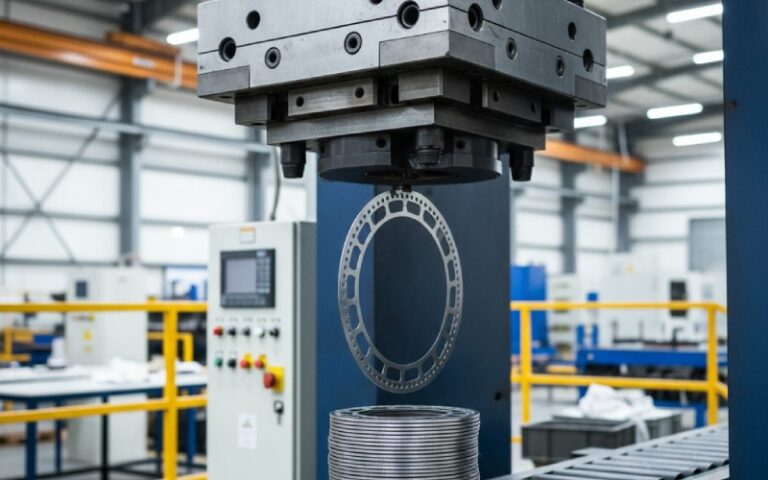
Let Sino's Lamination Stacks Empower Your Project!
To speed up your project, you can label Lamination Stacks with details such as tolerance, material, surface finish, whether or not oxidized insulation is required, quantity, and more.
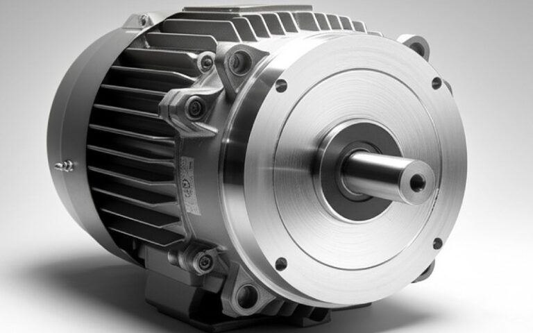
Air core motors are brilliant. Light. Fast. Efficient. When they fail, they can feel mysterious. This guide makes them less so. We’ll walk through symptoms, safe diagnostics, smart repairs, and lasting prevention. Short, clear steps. Thoughtful detail where it matters.
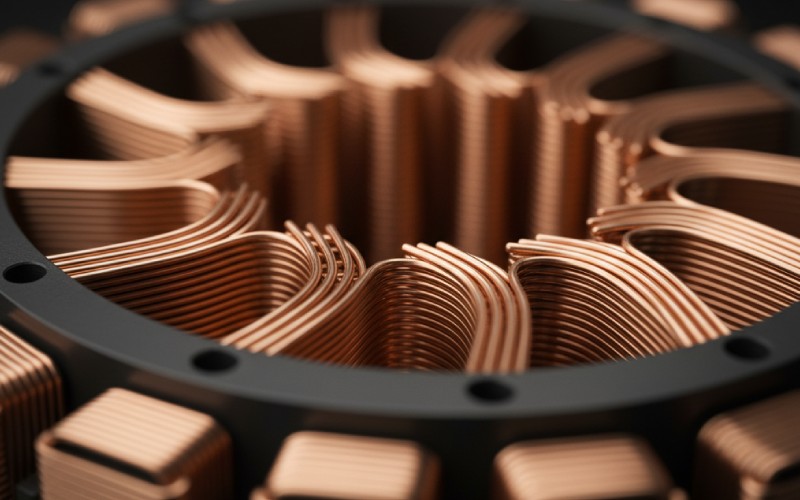
In an air core motor, the stator has little to no iron. That removes cogging and cuts eddy losses. It also changes how heat spreads and how failures show up. The result is silky motion, quick response, and sensitivity to abuse.
No iron means less thermal mass. Hot spots rise fast. A ding to a coil isn’t cushioned by steel. Adhesives and resin do more heavy lifting. Your repair choices must respect that.
Most issues boil down to three things: heat, vibration, and contamination. Heat cooks resins. Vibration works loose the coil pack, then frets the enamel. Contamination—salt, oils, iron dust—bridges turns or eats copper. Once one turn shorts, current spikes. Then more heat. Then the spiral.
Lock out power. Discharge caps. Remove propellers and belts. Protect magnets from loose steel. Work antistatic if you’ll touch the controller. And wear eye protection. Motors bite when they jump.
A good meter and LCR bridge tell you coil health. A milliohm meter catches imbalances. An oscilloscope plus a current probe shows phase symmetry. A small hot-air station softens adhesives without scorching enamel. Non-magnetic tweezers and plastic spudgers protect windings. A bore gauge helps check bearing fits.
Every mark tells you something. Brown varnish means heat. Silver dust? Bearings. Green fuzz? Copper salts from moisture. Uneven drag while hand-turning hints at a warped can or shifted coil pack. Listen. Feel. Note. Then measure.
Below is a compact table to connect what you see with what to test and how to respond.
| Symptom | Likely Cause | Quick Test | Risk Level | Typical Fix |
|---|---|---|---|---|
| Rough, gritty spin | Bearing wear or contamination | Remove belt/prop, spin by hand; check axial/radial play with dial indicator | Medium | Replace bearings; clean seats; re-grease if spec allows |
| Motor gets hot fast at light load | Partial turn short; phase imbalance | Phase-to-phase resistance with milliohm meter; LCR for Q-factor | High | Rewind or replace stator; do not run again before fix |
| Stuttering start, then cutout | One phase open; hall/sensor fault; ESC gate issue | Continuity per phase; scope back-EMF or hall outputs | Medium–High | Repair open joint; replace sensor; inspect ESC MOSFETs |
| Whine at specific RPM bands | Loose coil pack or magnet | Tap test; thermal cycling to see change; inspect adhesive lines | Medium | Re-bond coils or magnets with high-temp epoxy |
| Low torque, smooth but weak | Demagnetization or large air gap | Compare no-load Kv vs spec; inspect rotor can | High | Replace rotor; reset magnet arc/spacing |
| Random overcurrent faults | Conductive contamination | Megger to ground; inspect for metallic dust | High | Deep clean; conformal coat; install better filtration |
Start with non-invasive checks. Move to electrical tests with low energy. Only then apply heat or adhesives. Keep notes. Your notes reduce repeat faults.
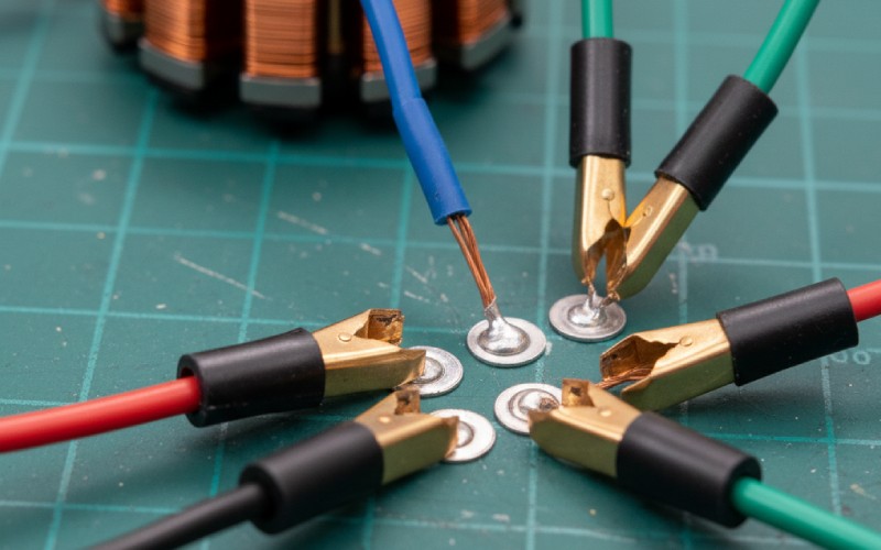
Cold joints and cracked lead-outs are common. Use proper strain relief. Reterminate with high-flex silicone wire and high-temp sleeving. When soldering near coils, shield enamel with a thin aluminum heat sink strip. Keep tip temps modest and dwell short. Afterward, re-impregnate exposed fibers with a compatible varnish.
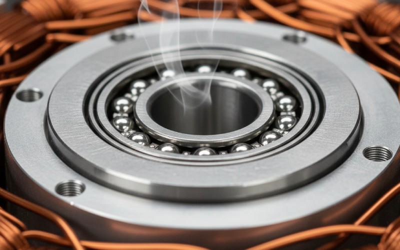
Air core designs depend on a consistent air gap. A bruised bearing seat or bent shaft ruins that. Replace bearings in pairs. Warm housings, chill bearings. Press on the correct race. Check runout with a dial indicator; under 0.02 mm TIR is a good general aim for small motors. Verify rotor can integrity; loose magnets demand immediate attention.
If resistance mismatch is clear, or the LCR Q-factor tanks, rewinding is on the table. Map everything first: wire gauge, turns per tooth, pattern, phase order, and lead routing. Count turns twice. Use the same or higher thermal class magnet wire. Tension evenly. Stake and tie with lacing before impregnation. Vacuum-impregnate if you can; it fills micro-voids and stops future fretting.
Vibration loosens bonds. Choose a high-temperature, low-shrink epoxy rated above your worst-case winding temp. Clean with solvent, then plasma or corona treat if available for better adhesion. Apply thin, even fillets. Cure fully. Do not shortcut cure times; partial cures creep.
Many “motor problems” are ESC problems. Check gate resistors and MOSFETs for shorts. Verify current shunt values. Update firmware to the vendor’s latest stable. Recalibrate throttle ranges. For sensored systems, ensure hall placement is consistent and shielded from magnetic noise.
Clean all mating surfaces. Set the air gap concentric. Use a threadlocker compatible with temperature and plastics nearby. Align sensors. Spin it with an external motor first and watch back-EMF symmetry. Then run at low current under its own drive. Step load in stages. Log temperature rise and ripple current. Listen for new noises. If it passes, label it with the work done and the new baseline numbers.
Dust and moisture kill air core motors early. So do loose mounts. Keep intakes filtered. Reroute cables so they don’t tug on lead-outs. Add vibration isolation where practical. Validate that firmware’s current limits match the motor’s continuous and peak ratings. Little tweaks, big life.
Monthly quick checks spot most trouble before it’s expensive. Quarterly, go deeper. Annually, tear down if the duty cycle is hard. Keep it boring, and the motor stays brilliant.
Air core motors reward gentle hands and good habits. Move from observation to measurement to action. Keep heat low, bonds strong, and gaps true. Do that, and the motor will give you back quiet power for a long time.