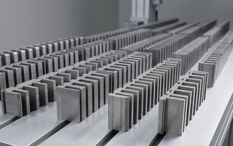
Let Sino's Lamination Stacks Empower Your Project!
To speed up your project, you can label Lamination Stacks with details such as tolerance, material, surface finish, whether or not oxidized insulation is required, quantity, and more.
If your transformer laminations run through an APQP-quality plan and a real PPAP, you stop arguing about losses, noise and repeatability. You just ship, measure, and keep tightening the spread. That is the whole point here.
Transformer laminations are quiet when the physics is under control: material, stress, geometry, insulation, magnetization path. The paperwork is there to keep those cause–effect links visible under pressure, not to satisfy a checklist.
APQP already gives you the structure for doing that across product and process development in a manufacturing environment. PPAP then acts as the formal proof that this structure actually produces laminations that respect the drawing, the core spec and the energy-efficiency targets every time, not just on a good day.
For transformer laminations specifically, the quality plan works when it translates these abstract tools into very ordinary things: which coil you bought, how you stamped it, how you relieved the stress, how you stacked it, and how you measured the result in watts, amps, and micrometres.
You already know the five APQP phases, so there is no need to name and explain them again. For laminations, it helps to quietly rewrite each phase with a single blunt question. What steel are we allowed to use. What stamping and annealing window actually keeps loss in band. How will we know the press has drifted. Which measurements are we ready to defend in front of a customer auditor.
The table below keeps it compact. It is not theory; it is the skeleton of the quality plan you actually maintain.
| APQP phase focus | Transformer lamination focus | Quality plan outputs that matter |
|---|---|---|
| Customer and product definition | Core design intent, energy class, no-load loss and magnetizing current targets, geometric envelope, noise and vibration expectations, insulation system | Product quality plan summary, list of special characteristics for laminations and cores, initial alignment on test methods and sample quantities |
| Product design and development | Lamination geometry, step-lap pattern, window and limb tolerances, steel grade and coating class, allowed stacking methods and jig concepts | Frozen drawings and specifications, special characteristic markings on lamination print and core spec, design FMEAs aligned with PFMEAs, preliminary test plans |
| Process design and development | Coil handling, slitting, stamping, deburring, annealing cycle, coating where applicable, stacking and clamping sequence, in-process measurement strategy | Process flow diagram that actually reflects the shop, PFMEA with physical failure modes (loss, burr, shorted laminations, core buzz), draft control plan including reaction plans |
| Product and process validation | Capability on core loss, magnetizing current, dimensions, burr height, coating resistance, stacking factor; validation across multiple coils and tool conditions | PPAP submission with capability studies, MSA on core-loss and coating-resistance equipment, full dimensional reports on worst-case laminations and built cores, run-at-rate evidence |
| Feedback, corrective action, improvement | Behaviour in the field: noise, hot spots, efficiency; behaviour in production: scrap patterns, tooling wear, coil variability | Closed-loop lessons learned, design standard updates, PFMEA and control plan revisions, updated material and process standards fed back into new RFQs and APQP launches |
The official APQP manual will not say anything about step-lap angles or coating resistance thresholds, but your lamination plan has to. That is where you separate yourself from generic “core tools” training.
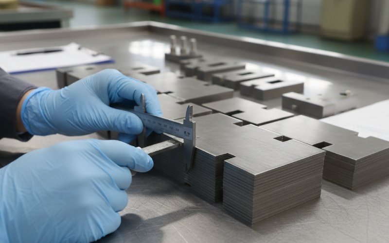
A transformer lamination control plan easily becomes a spreadsheet with more rows than thought. You can avoid that by starting from maybe six or seven characteristics that actually drive transformer behaviour: core loss at defined induction and frequency, magnetizing current, burr height, critical dimensions, stacking height or weight, insulation resistance between laminations, and in some segments noise at a defined test point.
Every other characteristic either supports these or exists to keep the process statistically stable. So the control plan should read almost like an argument. For each special characteristic, which process step influences it most, how is that step controlled, what do you measure there, what happens when it drifts. PFMEA and control plan stay in sync because they are both talking about the same physical failure modes, not generic “dimension out of spec” statements.
The difference from many online APQP examples is simple: they focus on form. You focus on how a strip of electrical steel becomes a low-loss core in a repeatable way.
Everything after this is downstream of steel quality and coating consistency. Electrical steel laminations start as thin cold-rolled strips that are stamped or cut into shape and then stacked into cores. The quality plan has to reflect this with a very explicit incoming section.
You define which standards you accept for grain-oriented or non-oriented steel, which loss classes, which coating classes, and what the coil-to-coil variation can look like before you even think about stamping. Typical references are IEC or ASTM grades and IATF 16949-based supplier systems; many lamination and electrical steel producers already operate under these schemes.
Core elements for this part of the plan are simple but non-negotiable. One, how each coil is identified and traced through slitting and stamping. Two, what you verify at goods receipt beyond the mill certificate: strip thickness, coating condition, basic loss check if you have a single-sheet or Epstein tester, sometimes even coating resistance. Three, how you react when these checks fail; not in an 8D template, but in terms of sorting, segregation, communication, and APQP updates.
If you do not treat incoming steel as part of your own APQP, you are relying on someone else’s plan, which may or may not understand transformer behaviour the way your customers expect.
High-speed presses create laminations at a rate the rest of the APQP paperwork cannot match. Tool wear changes burr height, geometry, and local stress patterns in ways that show up directly in core loss and noise. Your quality plan should assume that press conditions are the primary daily variable, more than raw material once the steel family is stabilised.
Instead of long paragraphs about generic process control, write down how you detect drift in the press. This might be a defined burr-height sampling plan, dimensional checks on features that are sensitive to die wear, or even acoustic signatures of the press stroke if you like more advanced methods. Capability studies in PPAP should treat these as key characteristics, not afterthoughts tacked onto the submission.
The process flow diagram is helpful here only if it actually shows the real loops: tool maintenance, trial hits, first-off inspection, and approvals to start mass stamping. If these flows are edited out for simplicity, the PFMEA and control plan will talk about a fantasy process.
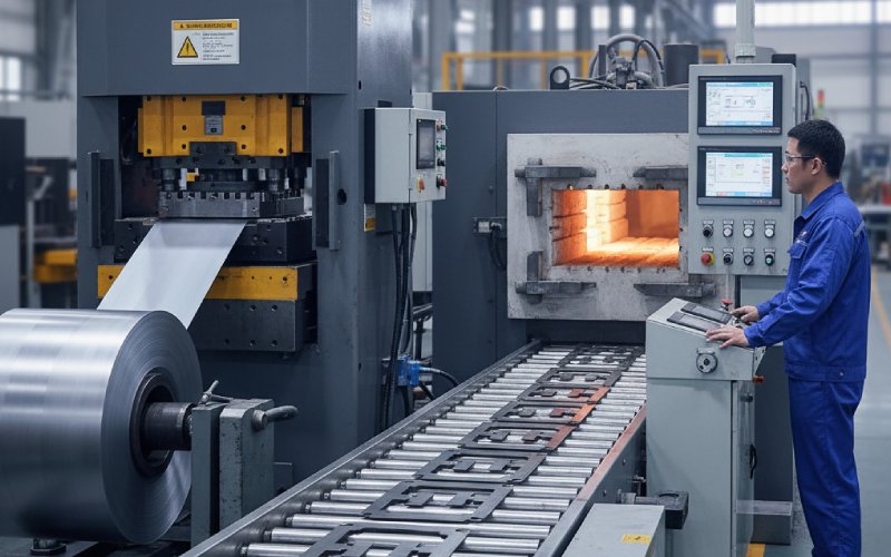
Stress-relief annealing turns stamped electrical steel into something closer to the datasheet values. Cycle design, loading patterns in the furnace, and atmosphere control together decide how close you get. The APQP quality plan should treat annealing as a specialised process, with its own qualification logic, not just a box between stamping and stacking.
For many lamination suppliers, it makes sense to borrow thinking from furnace assessment standards used in automotive heat treatment and adapt them to transformer-oriented metrics. You define the recipe, you qualify it with test coupons or test cores, and you lock the key parameters in the control plan. Then you connect that to actual core-loss and magnetizing-current results in PPAP runs, to show that the combination of stamping plus annealing is stable.
When coils change, or die design changes, or core geometry changes significantly, this is one of the first areas you revisit in the quality plan. That review needs to be automatic, not driven by a complaint.
A perfect lamination can still end up in a noisy or inefficient transformer if stacking and clamping are inconsistent. Step-lap patterns, overlap lengths, stacking factor and clamping pressure all affect flux distribution and noise. None of this surprises you, but it often hides in work instructions rather than in the formal quality plan.
Bring it into APQP. Treat stacking as a process with special characteristics, not just assembly. Define what “correct pattern” means in measurable terms, how operators verify it during build, and how incoming laminations are staged to support it. Then decide what you actually measure on finished cores in production: mass, dimensions, maybe a quick core-loss screening test before the cores leave the lamination plant.
If your organisation produces complete transformers, the handoff between lamination plant and transformer assembly should be described in the APQP control plan as well. It is not enough to say “cores tested at final transformer test” if that is the first time anyone checks whether the lamination process stayed in control.
Most PPAP packages look similar from a distance: design records, process flow, PFMEA, control plan, MSA, capability, initial samples, and the rest. For transformer laminations, the difference is in how much of that content explicitly talks about electromagnetic performance and not just geometry.
Design records should tie directly to core specifications: window and limb dimensions, step-lap patterns, steel grade, and coating class specified in a way that can be traced back to the steel producer’s datasheet and standards. Flow diagrams and PFMEAs should list failure modes like “core loss above X W/kg at Y T, Z Hz”, “magnetizing current above limit at rated voltage”, “audible noise above agreed level”, “laminations shorted through damaged coating” as primary items, not footnotes.
The control plan submitted with PPAP should read almost like a test plan for those failure modes. It states which process steps control them, which measurements are taken at which frequency, what the reaction plans are, and how traceability is maintained from coil to lamination bundle to transformer core. Capability studies should include, where practical, statistical evidence on core loss and critical dimensions, not just a long list of minor dimensions that are easy to hold.
When your PPAP tells this story cleanly, customer SQEs can read it and see how the production process protects their design intent, without guessing how lamination physics is tied in.
Many lamination quality plans drift toward heavy dimensional metrology and very light functional testing. It is understandable, because CMMs are convenient and core-loss testers are slower, noisier, and sometimes messy. But transformers do not care whether a small non-critical slot is perfectly centred; they care about losses, excitation current, noise, and fit.
A practical measurement strategy in your APQP deliverables usually has two layers. One layer is the functional tests that prove the process still produces good cores: core-loss tests on defined sample frequencies and inductions, magnetizing current checks, basic noise checks where noise is critical. The other layer is the process indicators that are easier to measure at high frequency and are well-correlated with those functional results: burr height, strip thickness, key dimensions, simple electrical resistance between laminations, press-monitoring metrics.
MSA work should focus on the functional layer first, because that is where poor gage systems hurt you most. A core-loss test with poor repeatability or operator influence will confuse every capability calculation that depends on it, and your PPAP will look better on paper than in reality.
A quality plan that exists only as a set of APQP and PPAP documents is fragile. People remember shortcuts, not paragraphs. The lamination environment is noisy, fast, sometimes hot, with production pressure that does not wait for an SQE review.
So the plan has to be present in daily routines. First-piece approvals at the press that mirror the control plan checks. Clear limits and reactions at incoming steel inspection. Regular layered audits that ask simple questions such as “show me how you know this burr height is acceptable” or “which coil did this stack come from”. Quick feedback loops when a transformer test station far downstream sees drift in core loss or noise.
None of this is original, but writing it into the APQP control plan and then keeping it updated forces alignment. It also makes customer audits much simpler, because every question can be answered by showing how plant routines connect back to the documented plan.
Look at your last few serious issues related to laminations and cores. You will recognise patterns. Losses slightly above target at certain voltage points, higher noise in specific transformer ratings, local hot spots in infrared, mechanical fit problems in cramped tanks, coating breakdown after aggressive drying cycles, sometimes even shipment mixes between similar lamination sets.
Each of these, if unpacked, usually maps back to a small gap in APQP or PPAP. A missing special characteristic, a weak incoming-spec definition for steel, an annealing change not treated as a significant process change, a stacking variation not covered in work instructions, an MSA study skipped for a critical gage.
Your quality plan improves when you routinely take these issues and ask a simple question: where in the APQP and PPAP artefacts should this have been visible. Then you write that answer back into future projects. Over time, the lamination-specific knowledge accumulates in the plan rather than in individual engineers’ heads.
If you want a simple way to apply this on your next lamination project without rewriting your whole system, you can think in four passes through the same plan.
Before RFQ, you document what you need from steel suppliers, what test methods you and the customer will accept for losses and magnetizing current, and how you will define special characteristics on drawings. At design freeze, you lock the geometry and step-lap pattern with enough detail that process engineers can design stamping and stacking without assumptions. Before PPAP submission, you verify that PFMEA, control plan, and test plans talk about core loss, noise and coating behaviour as first-class items. After SOP, you treat each serious issue as an experiment in improving the plan for the next launch, not only as a containment problem.
The official manuals call this continuous improvement. In a lamination plant, it is just the habit of not wasting hard-earned experience.
A quality plan for transformer laminations is less about inventing new tools and more about using APQP and PPAP in a way that respects transformer physics and production reality at the same time. The more your documents talk about watts, amps, burrs and coils, and the less they talk in generic phrases, the closer you are.
If your next project ends with a PPAP where the submission feels like a compact, honest description of how steel becomes stable cores in your plant, then the plan is doing its job. The rest is running it every day and quietly tightening the variation cycle by cycle.