Let Sino's Lamination Stacks Empower Your Project!

To speed up your project, you can label Lamination Stacks with details such as tolerance, material, surface finish, whether or not oxidized insulation is required, quantity, and more.

Building a Costed BOM Around the Stator and Rotor

The stator and rotor together usually dominate both material and processing cost, so if you build your bill of materials (BOM) around them instead of treating them as a black box, you get far more control over margin, risk, and design trade-offs.

Most public articles either stay generic (“laminations and copper are important”) or get lost in academic cost modeling. This guide aims to sit in the middle: practical enough to drive an Excel model today, and deep enough that your costed BOM is defensible in design reviews and sourcing negotiations.


  • What you’ll learn in this article
    • A mental model for structuring a costed BOM around stator and rotor
    • How to decompose stator and rotor into costable sub-assemblies
    • Typical line items and cost drivers you should never leave “bundled”
    • How to connect engineering knobs (slot fill, lamination thickness, magnet grade) to their cost impact
    • A simple table structure you can drop into your own costing spreadsheet

1. Start With the Machine, Not the Spreadsheet

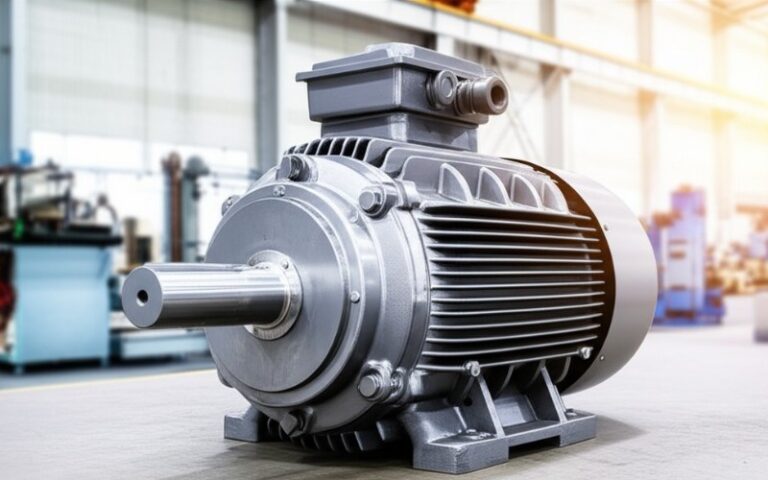
Before touching a BOM template, zoom out: what kind of machine are you costing? A permanent magnet synchronous motor (PMSM) for an EV, an inner-rotor BLDC servo, or a bog-standard induction motor all have very different cost structures — especially in their stator and rotor.

Two decisions dominate everything that follows:

  1. Topology (PM vs induction vs wound field, inner- vs outer-rotor, axial vs radial flux)
  2. Rating and duty (continuous vs intermittent, speed, torque, duty cycle, environment)

These choices define whether your cost is magnet-heavy, copper-heavy, or steel-heavy — and what level of tolerances, balancing, and testing are appropriate. For example, an outer-rotor BLDC hub motor may spend more on magnets and lamination diameter, while a high-speed inner-rotor PM machine spends aggressively on precise laminations, sleeves, and balancing.

Once that context is clear, your costed BOM is no longer an abstract spreadsheet; it’s a structured narrative of how this specific machine turns money into torque.


  • Key design decisions to lock before you build the BOM
    • Motor type and topology (PMSM, induction, switched reluctance; inner vs outer rotor)
    • Power, base speed, peak/continuous torque and duty profile
    • Cooling concept (air, liquid, hydrogen, direct-cooled windings)
    • Target efficiency class / regulatory requirements
    • Volume and maturity assumptions (prototype vs SOP, annual build rate)
    • Environmental constraints (IP rating, corrosion, shock/vibration)
    • Integration level (delivering bare stator/rotor stacks vs fully wound and tested assemblies)

Disassembled motor stator and rotor

2. Decomposing the Stator: From “One Line Item” to a Costed Stack

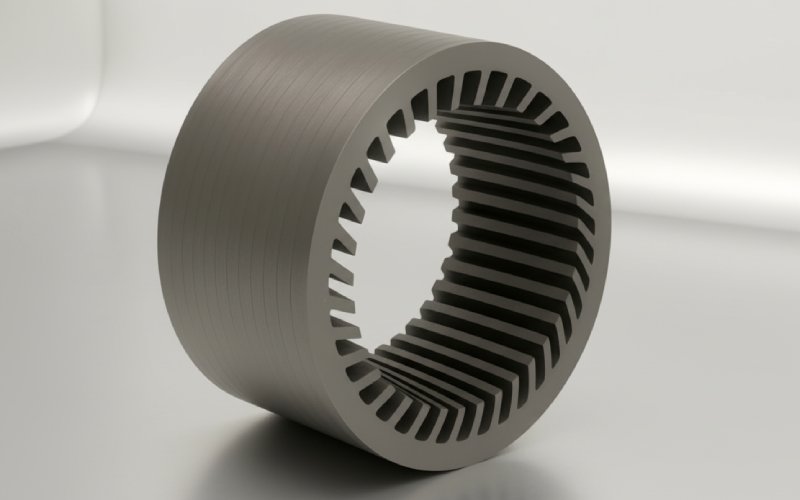
If you look at teardown-based cost studies and OEM “motor CBOMs” (costed BOMs), you’ll see that stator costing is never just “stator – $X”. It’s a set of tightly related but separable cost buckets: laminations, insulation, copper, impregnation, machining, and tests.

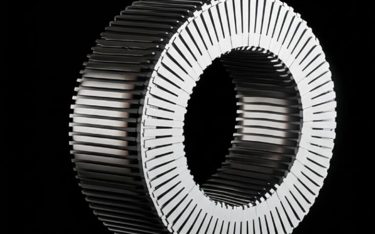
At a physical level, almost all modern stators are some variant of:

  • Core made from thin electrical-steel laminations, usually 0.15–0.65 mm thick, stacked and bonded or interlocked.
  • Windings (round wire, hairpin, or litz) placed into slots, guided by slot liners and wedges.
  • Insulation system (slot liners, wedges, tapes, varnish/VPI resin) that must survive decades of thermal and electrical stress.

A good costed BOM makes these physical realities explicit. Instead of one vague “stator” line, you model: raw steel mass and scrap factor, press-tool amortization, winding method, impregnation process, and the test regime required by your customer spec.

Done properly, you can now ask informed questions like: “What if we move from segmented cores to a simple laminated stack?” or “What is the cost per percentage point of slot fill improvement?” and see answers in the CBOM rather than in hand-waving.


  • Typical stator BOM line items (that deserve their own rows)
    • Lamination steel
      • Electrical-steel grade (Si content, core loss spec)
      • Net mass × scrap factor (punching / trimming waste)
      • Lamination thickness (thinner → lower loss, higher material & tooling cost)
    • Core manufacturing
      • Stamping / laser cutting cost per lamination
      • Stack bonding or interlocking operations
      • Post-stack machining / grinding for OD/ID and stack height tolerance
    • Windings
      • Copper (or aluminum) mass based on slot fill factor and conductor choice
      • Winding process (manual, needle, flyer, hairpin bending and welding)
      • Lead termination hardware (lugs, busbars, insulation boots)
    • Insulation system
      • Slot liners, wedges, phase separators (Nomex, mica, etc.)
      • Varnish or VPI resin consumption and cycle time
      • Curing/oven time and energy
    • Quality and test
      • Surge, hipot, partial discharge, resistance measurement
      • Dimensional checks and core-loss test on sample stacks

3. Rotor BOM: Where Cost and Risk Like to Hide

If the stator often dominates copper cost, the rotor frequently dominates risk: magnets that move with commodity markets, high-speed mechanical integrity, and manufacturing yield.

For induction machines, you might have a relatively “simple” squirrel-cage rotor — laminations plus cast or bar-and-ring conductors — but the die casting or bar brazing process and the required straightness and balance still carry meaningful cost.

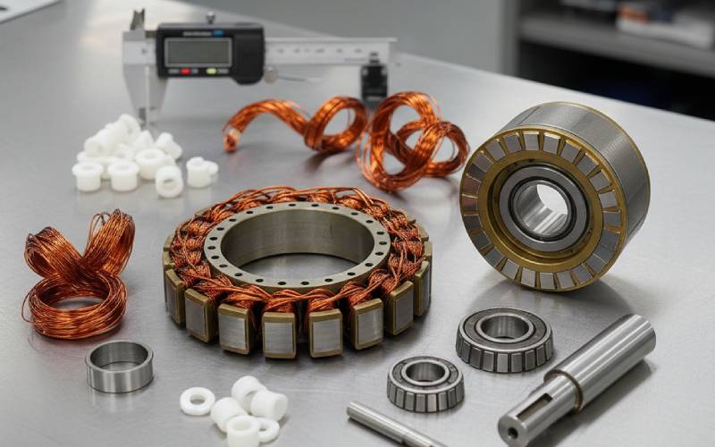
For PMSMs and BLDC machines, the rotor stack is where your BOM feels every rare-earth price spike. Magnet volume, grade, coating, retention method (sleeves, cans, potting), and overspeed/burst requirements all translate to concrete cost lines that should stand on their own instead of lurking in a single “rotor – $Y” entry.

On top of that, you have the shaft, keys, couplings, and any integrated position sensing elements — all small individually, but material when multiplied by annual volume.


  • Typical rotor BOM line items
    • Rotor laminations
      • Electrical steel grade and thickness (often thinner for high-speed IR designs)
      • Punching/stamping plus stacking method (welded, bonded, interlocked)
      • Skewing steps (segmented skew stacks or skewed punch patterns)
    • Magnetic system (PMSM / BLDC)
      • Magnet material (NdFeB, ferrite, SmCo), grade, and coating
      • Magnet volume and arc coverage vs required torque
      • Retention: sleeves (carbon fiber / steel), cans, or potting
      • Magnetization and handling (fixtures, safety, QA)
    • Conductor system (induction / wound-rotor)
      • Copper or aluminum cage (casting or bar + ring)
      • End-ring machining and any heat-treatment
      • Brazing or casting fixtures and consumables
    • Mechanical elements
      • Shaft forging or bar stock, turning, grinding
      • Keyways, balancing features, threads
      • Retaining rings, shrink fits, and associated tooling
    • Balancing and test
      • Dynamic balancing (machine time, trial weights)
      • Overspeed proof test (if required)
      • Runout measurements and documentation pack

4. Turning Pieces Into a Costed BOM

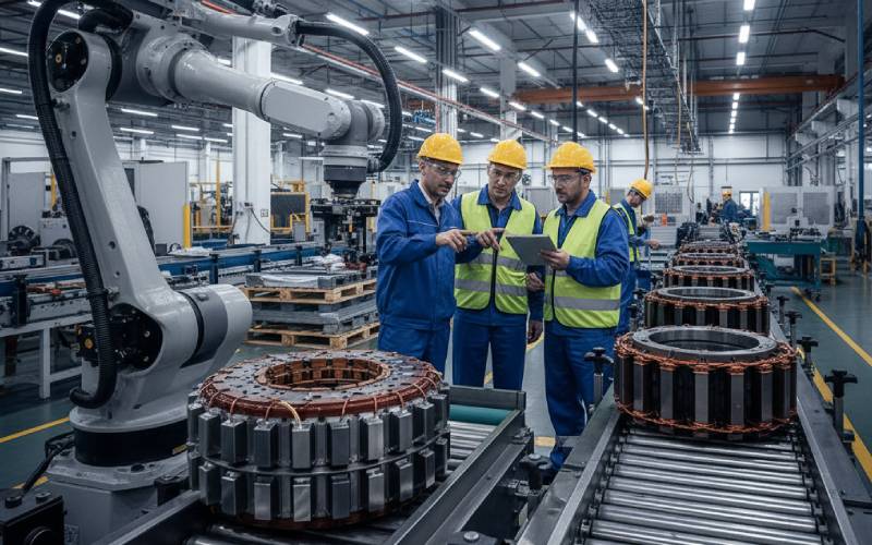
With stator and rotor broken into meaningful chunks, the next step is to express them in a consistent CBOM structure that links quantities (kg, seconds, machine-hours) to money. Most industry cost models for motors follow a similar pattern: each line item has material, process, and overhead components, with tooling and one-time engineering treated separately and amortized over an assumed volume.

Here’s a simplified table you can adapt directly into your BOM sheet. Numbers here are placeholders — the structure is what matters:

Sub-assemblyItem categoryExample line itemPrimary cost driversNotes for stator/rotor CBOM use
StatorRaw materialElectrical steel laminationskg × price/kg × scrap factorScrap factor depends on punching pattern and nest efficiency.
StatorConversion (labor)Lamination stamping and stackingPress time, operator time, OEETie to press tonnage and strokes/min.
StatorDirect materialCopper windingsSlot fill, conductor choice, copper price curveModel scenario with Al instead of Cu.
StatorProcessWinding and terminationCycle time, automation levelDistinguish manual vs robotic lines.
StatorProcessVPI / impregnationResin mass, tank time, oven timeBatch size has huge effect on cost.
RotorRaw materialMagnets (NdFeB)Volume × grade priceTreat magnet cost as separate sensitivity input.
RotorConversionMagnet insertion and curingHandling, fixtures, cure timeInclude scrap/yield loss for chipping or demag.
RotorProcessDynamic balancingBalancing machine hoursOften surprisingly large at low volume.
RotorRaw materialShaft and retaining ringsMaterial grade, machining allowanceWatch tolerance creep → rework cost.
SharedNRE/toolingStamping dies, winding tooling, jigsTool cost ÷ lifetime volumeKeep these explicit, not buried in “overhead”.

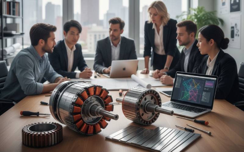
Once this structure exists, “what-if” design conversations become spreadsheet edits instead of arguments: thinner laminations, different magnet topology, segmented stator teeth — they all show up as parameter tweaks and you can see the impact on cost per kW or cost per Nm.


  • Common CBOM mistakes that quietly distort stator/rotor cost
    • Rolling magnet cost into a single “rotor assembly” line instead of tracking it explicitly
    • Ignoring punching/lamination scrap factors (especially with complex tooth shapes)
    • Treating high-speed balancing and overspeed tests as negligible instead of dedicated cost lines
    • Burying VPI and insulation costs in a generic “assembly labor” bucket
    • Forgetting to amortize tooling and test-rig investment over realistic volumes (not the volume you hope for)
    • Using a single “copper price” without modeling sensitivity to slot fill factor and conductor choice

Motor stator and rotor production line

5. A Practical Workflow You Can Use Tomorrow

To pull this all together into something actionable, it helps to follow a repeatable workflow rather than re-inventing your CBOM every project. Think of it like a checklist you walk through with design, manufacturing, and purchasing in the same (real or virtual) room.

  1. Freeze the motor definition just enough. Capture topology, ratings, cooling, and volume assumptions in a one-page “motor charter”.
  2. Sketch the stator and rotor physically. On a whiteboard or in CAD, draw which parts belong to which sub-assembly. Everything you can point at gets its own BOM line.
  3. Build the CBOM skeleton. Start from a table like the one above, add company-specific cost buckets (e.g., plant overhead, logistics, warranty reserve).
  4. Parameterize the physics. Link lamination mass, copper mass, magnet volume, and cycle times to your electromagnetic and mechanical design models where possible, even if via simple analytic approximations or FEM post-processing.
  5. Plug in supplier and internal process data. Use quotes, historical purchase prices, and machine-hour rates rather than guesses; update periodically.
  6. Run sensitivities, not single points. Treat magnet price, copper price, volume, and scrap factors as sliders and map how they affect cost per unit and per kW.
  7. Close the loop with design. Use the CBOM to argue design changes (“if we accept a slightly larger diameter, we can save 10% magnet volume by going outer-rotor”) rather than trying to shave pennies off fixed drawings.

If you follow this pattern, your “costed BOM around the stator and rotor” stops being an after-the-fact accounting artifact and becomes a design tool: one that lets you reason clearly about where each dollar goes, why it’s there, and how to move it without breaking the motor.

And that’s the real competitive edge — not just knowing your stator and rotor cost, but being able to shape that cost with engineering intent.

Share your love
Charlie
Charlie

Cheney is a dedicated Senior Application Engineer at Sino, with a strong passion for precision manufacturing. He holds a background in Mechanical Engineering and possesses extensive hands-on manufacturing experience. At Sino, Cheney focuses on optimizing lamination stack manufacturing processes and applying innovative techniques to achieve high-quality lamination stack products.

New Product Brochure

Please enter your email address below and we will send you the latest brochure!

en_USEnglish

Let Sino's Lamination Stacks Empower Your Project!

To speed up your project, you can label Lamination Stacks with details such as tolerance, material, surface finish, whether or not oxidized insulation is required, quantity, and more.