Let Sino's Lamination Stacks Empower Your Project!
To speed up your project, you can label Lamination Stacks with details such as tolerance, material, surface finish, whether or not oxidized insulation is required, quantity, and more.
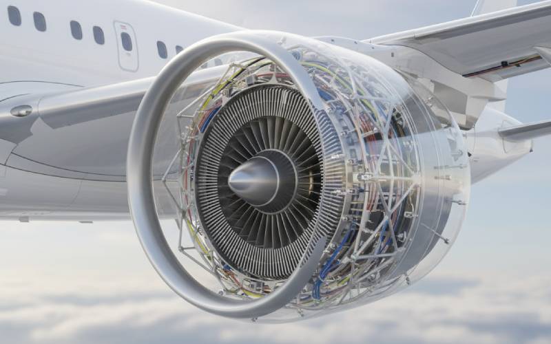
Aerospace stator and rotor using Co-Fe steel: when it’s worth it
If you work on aerospace electrical machines, you’ve probably had that meeting.
Someone says, “What if we go to Co-Fe for the stator and rotor? We could shrink the machine and hit the power-density target.”
Someone else says, “Sure, if you’ve got a spare budget line for exotic metals and a test campaign for a new thermal profile.”
This article is for that exact moment.
Instead of just listing properties, we’ll walk through how Co-Fe actually changes your stator and rotor design, where aerospace teams are already betting on it, and a practical checklist for when the performance gain is actually worth the pain.
Ultra-short answer: Co-Fe is worth it when…
You are power-density or weight limited and already squeezing silicon steel to ~1.6–1.7 T in the teeth and back iron.
The machine runs at high speed and/or high temperature, where high saturation and a high Curie point buy you rotor diameter or safety margin.
You can translate the higher flux density (and resulting smaller core) into system-level wins: less structure, smaller gearbox, lower cooling mass, or better payload/range.
Your program can live with higher material cost, more complex manufacturing, and tighter process control on lamination thickness and heat treatment.
Table of Contents
Why aerospace cares about Co-Fe in the first place
In electric aircraft and more-electric engines, Co-Fe alloys show up because they do one thing extraordinarily well: they carry a lot of flux without saturating.
Modern Fe-Co-V alloys like Hiperco-type grades or 49% CoFe laminations reach saturation flux densities around 2.3–2.4 T, compared with ~1.6–1.8 T for traditional non-oriented silicon steel.
That difference is massive: for a given torque or power, you can:
shrink tooth width,
shorten the stack,
or raise torque/power without changing the envelope.
Co-Fe alloys also typically:
have higher Curie temperatures (Hiperco ~980 °C vs ~450–750 °C for many Ni-Fe and Si-Fe steels), helping maintain magnetic performance in hot zones near engines or inside tightly packed power units;
and can offer lower core loss at comparable flux density when carefully annealed and used at appropriate frequency.
That’s why a 2024 review explicitly notes that electric aircraft manufacturers often select Co-Fe over Fe-Si to hit demanding induction, loss, and permeability targets in high-performance machines.
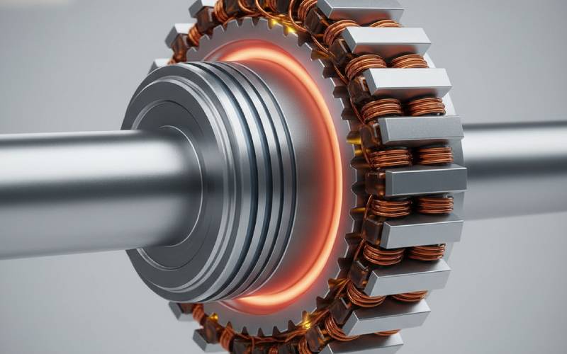
What Co-Fe “feels like” in your design compared with other core materials
Silicon steel (NOES)
Good all-rounder, low cost, low core loss, saturation around 1.6–1.8 T.
Dominates mass-market stators and rotors for EVs and industrial motors.
Ni-Fe alloys
Very high permeability and very low loss at low fields, but saturation is modest (often ≤1.5 T) and Curie temperature is relatively low.
Great for sensors, transformers, and magnetic shielding—not usually the first choice for torque-dense aerospace machines.
Co-Fe alloys (with or without V)
Highest saturation of common soft magnetic alloys (≈2.3–2.4 T).
Used in high-end motors, generators, and magnetic bearings where performance and weight trump raw material cost.
Quick comparison: Co-Fe vs Si-Fe vs Ni-Fe for aerospace stator/rotor cores
Think of this as a sanity-check table rather than a datasheet. Exact numbers depend on grade, thickness, and processing, but the relative trends are robust.
Attribute
Co-Fe (≈49% Co-Fe-V)
Advanced Si-Fe (NOES)
Ni-Fe (≈48% Ni, Magnifer-type)
Typical saturation flux density, Bs
~2.3–2.4 T
~1.6–1.8 T
~1.5 T (best high-sat grades)
Curie temperature (order of magnitude)
~900–980 °C
~700–800 °C (varies with Si content)
~400–500 °C
Core loss at moderate frequency (for similar B)
Often comparable or lower than Si-Fe when optimized and thin-gauged
Very good; EV-grade NOES tuned for low loss
Excellent at low frequency/low flux; not optimized for high-flux traction machines
Electrical resistivity
Lower than Si-Fe → higher eddy current risk at high frequency/induction
Higher than Co-Fe → better high-frequency loss behavior
Intermediate; often higher than Co-Fe but lower Bs
The key takeaway: Co-Fe buys you flux density and temperature headroom that you simply cannot get from Si-Fe or Ni-Fe. The question is whether your program really cashes those chips in.
How those numbers show up at aircraft level
Smaller, lighter machines: Higher Bs means less iron for the same flux. That can cascade into lighter mounts, smaller nacelles, or more payload/range.
Higher torque/power density: In starter-generator or hybrid-propulsion roles, Co-Fe cores help push torque density beyond what EV-style Si-Fe stacks can support without saturating.
Survivability in hot locations: High Curie temperature keeps magnets “alive” near engines and in tightly packed power units where cooling air is limited.
Frequency flexibility: With the right lamination thickness, Co-Fe can maintain acceptable losses at elevated electrical frequencies typical of high-speed aerospace machines.
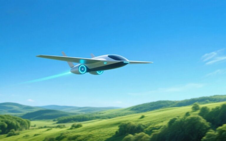
Where aerospace is already saying “yes” to Co-Fe stator and rotor stacks
If you look at recent aerospace literature and supplier data, you’ll see Co-Fe alloys in a few very specific corners:
high-speed starter-generators on engine spools,
APUs and more-electric power units,
experimental or demonstrator electric propulsion systems,
and magnetic bearings or high-speed compressors.
Manufacturers of iron-cobalt alloys openly position their Co-Fe stator and rotor stacks as enablers for high-power-density aircraft generators and APUs, claiming roughly 25% higher induction and ~30% lower loss than conventional electrical steel in comparable designs.
Academic and industry studies of high-speed machines for aerospace and magnetic bearings repeatedly converge on Co-Fe as the “top right” corner of the performance map: highest saturation plus adequate mechanical properties when thermally processed correctly.
Common aerospace scenarios where Co-Fe earns its keep
Starter-generators tied to engine speed
Very high electrical frequency and rotor speed.
Tight radial and axial space in the engine.
Huge penalties for added weight on rotating structures.
Wing or fuselage-integrated propulsion motors
Power-density targets that Si-Fe cannot meet without unacceptable saturation.
Strong system-level incentives for smaller nacelle or fan diameter (drag, aero, structures).
APUs and more-electric power units
Need to pack significant generating capability into the smallest possible envelope.
Hot installation environment where high Curie temperature is reassuring.
Magnetic bearings / high-speed compressors
Require very high forces in limited volume; Co-Fe’s saturation advantage turns directly into load capacity.
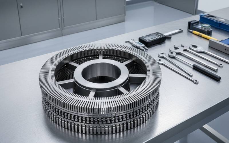
What really changes in your stator and rotor when you switch to Co-Fe
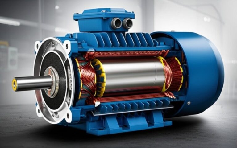
From a distance, a Co-Fe stator stack looks exactly like a silicon-steel one: thin laminations, insulation coating, slots, back-iron.
Electromagnetically and mechanically, though, the design space shifts.
Flux distribution and tooth loading
With Bs ≈ 2.3–2.4 T, you can operate at significantly higher peak induction in teeth and back iron before saturation clamps your torque or power.
That lets you shrink tooth width or core length, or run more aggressive slot/pole combinations without hitting a hard ceiling.
Thermal profile
Co-Fe’s lower resistivity means eddy current losses climb faster at high frequency and high flux density than in Si-Fe if lamination thickness isn’t reduced.
The payoff is that even at elevated temperatures, Co-Fe retains its magnetization much more effectively than Ni-Fe or standard Si-Fe.
Mechanical limits
High-speed rotors in Co-Fe often use specialized grades (e.g., VACODUR or Hiperco HS) that balance saturation with tensile strength via tailored annealing.
The rotor’s burst margin and bending stiffness can actually improve compared with some Si-Fe solutions, provided your heat-treat window is tightly controlled.
System-level knock-ons
Smaller cores can mean shorter cooling paths, different winding choices (e.g., more copper fill in a smaller slot), and altered thermal bottlenecks.
Structures, mounts, and NVH characteristics can all change when you shift mass inward and reduce iron volume.
Concrete design moves you can make with Co-Fe
Raise allowable flux density in teeth/back iron
Move design limit from ~1.6–1.7 T up toward ~2.0–2.1 T in the working region, keeping margin to true saturation.
Trim iron volume
Narrow teeth, reduce yoke thickness, or shorten the stack to hit a weight target while maintaining torque.
Trade iron for copper (or vice versa)
With more flux capability, you can sometimes reduce current density and copper loss while maintaining performance.
Use thinner laminations to manage loss
Because Co-Fe has lower resistivity, high-speed machines often require thinner laminations than equivalent Si-Fe designs to keep eddy losses under control.
Push speed with high-strength grades
Pair high-saturation Co-Fe with high-strength variants and appropriate heat treatment for magnetic bearings and ultra-high-speed rotors.
The uncomfortable bits: cost, manufacturability, and risk
This is where many programs back away from Co-Fe.
Co-Fe’s biggest drawback is not physics. It’s economics and process sensitivity.
Material cost & supply
Co-Fe alloys are explicitly called out in the literature as “more expensive” due to their high cobalt content.
Cobalt pricing and sourcing carry geopolitical and ethical baggage, which some OEMs now treat as strategic risk.
Processing difficulty
Co-Fe laminations are more sensitive to the full process chain (stamping/laser cutting, stress, annealing, coating) than many Si-Fe grades. Magnetic properties are tightly linked to the heat-treat schedule.
Lower resistivity means that if you don’t go thin enough on lamination gauge—or if coating/insulation is inconsistent—eddy losses balloon at aerospace-typical frequencies.
High-frequency behavior is a double-edged sword
At moderate frequencies and wisely chosen flux densities, Co-Fe can actually exhibit lower total loss than Si-Fe.
Push B and f too hard without adjusting lamination thickness, and the eddy-current term dominates; several comparative studies show cross-over points where Si-Fe wins again at very high induction/frequency combinations.
Program risk
New material + new supplier + new anneal + new stator/rotor geometry is a lot of “new” in one stack for a safety-critical aerospace application.
If earlier prototypes use Si-Fe, switching late to Co-Fe often triggers re-qualification of thermal models, mechanical margins, and sometimes electromagnetic compatibility.
Questions to pressure-test your Co-Fe business case
1. What is my iron utilization today?
If your Si-Fe stator/rotor is only running 1.3 T in critical paths, Co-Fe probably won’t move the needle enough to pay back the cost.
2. Is weight truly mission-critical here?
If this generator sits in a non-rotating bay with modest structural penalties, shaving a few kilograms may not justify Co-Fe.
If it’s spinning on an engine spool or hanging under a wing, every kilogram is amplified through structures and drag.
3. What electrical frequency am I really operating at?
Up to a few hundred Hz, with thin laminations, Co-Fe can be loss-competitive or better.
In the kHz range, you may be better served by advanced Si-Fe, amorphous, or nanocrystalline approaches.
4. How mature is my supplier ecosystem?
Do you have at least one Co-Fe lamination supplier who already supports aerospace customers and understands your qualification requirements?
5. Can I point to a clear system-level win?
Examples: one less cooling loop, smaller nacelle, higher payload, a specific mission profile that becomes possible.
If the benefit only shows up as “nicer numbers in a datasheet,” that’s usually not enough for certification and procurement teams.
A simple mental model: “three green lights” for Co-Fe stator & rotor cores
Imagine a traffic-light test. You only move to Co-Fe when all three of these are green:
Physics green – You are visibly iron-limited (saturation or temperature) in an Si-Fe design, and Co-Fe clearly removes that bottleneck.
System green – The resulting mass/volume reduction or performance gain unlocks mission-level value (range, payload, redundancy, packaging).
Program green – You have suppliers, budget, and schedule to qualify Co-Fe, plus a plan for the higher material and manufacturing complexity.
If any one of those stays red, it’s usually smarter to:
refine your Si-Fe design (better grade, thinner laminations, improved cooling),
or consider hybrid approaches (e.g., Si-Fe in most of the core with Co-Fe only where flux density peaks are unavoidable).
So… when is Co-Fe “worth it” for aerospace stator and rotor stacks?
Here’s the short, honest version:
If you’re designing a high-speed, high-power-density aerospace machine—starter-generator, APU generator, or integrated propulsion motor—and your Si-Fe design is already pressed against saturation and thermal limits, Co-Fe is absolutely worth a serious trade study.
If you’re working on moderate-speed, packaging-friendly systems where you’re not iron-limited, Co-Fe usually looks like an expensive way to make the performance spreadsheet slightly greener.
Used well, Co-Fe is less of a “fancy material upgrade” and more of a strategic lever. It lets you bend the usual tradeoff curve between weight, power, and thermal margin in ways that standard electrical steels simply cannot.
The job of the stator and rotor designer in aerospace isn’t to love Co-Fe or hate it—it’s to know exactly when that lever is the one that makes the whole aircraft better.
If you’d like, I can help you sketch a Co-Fe vs Si-Fe concept for your specific machine (power, speed, voltage, envelope) and turn this general guidance into a project-level decision.
Cheney is a dedicated Senior Application Engineer at Sino, with a strong passion for precision manufacturing. He holds a background in Mechanical Engineering and possesses extensive hands-on manufacturing experience. At Sino, Cheney focuses on optimizing lamination stack manufacturing processes and applying innovative techniques to achieve high-quality lamination stack products.
New Product Brochure
Please enter your email address below and we will send you the latest brochure!
Let Sino's Lamination Stacks Empower Your Project!
To speed up your project, you can label Lamination Stacks with details such as tolerance, material, surface finish, whether or not oxidized insulation is required, quantity, and more.