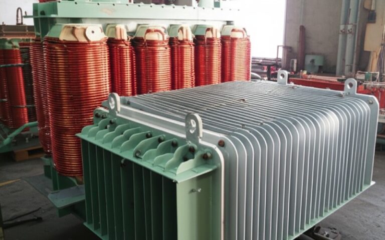
Let Sino's Lamination Stacks Empower Your Project!
To speed up your project, you can label Lamination Stacks with details such as tolerance, material, surface finish, whether or not oxidized insulation is required, quantity, and more.
The joint geometry is quietly trading watts, VA and dB every time you raise the flux density.
So this piece stays closer to how lamination stacks behave on the shop floor and in the test bay, not in a magnetics lecture.
Keep it short:
Same steel, same induction, different pattern of pain.
You’ve seen the marketing claims; here’s a more grounded way to think about it.
Across lab work, patents, and field data:
Mechanisms you already know, but let’s list them so the trade-offs are clear:
So: “step-lap = always lower loss” is mostly true when geometry and cutting are under control. When they aren’t, joint style matters less than process discipline.
The noise story is usually more visible to end users than the watt loss.
From field measurements and controlled tests:
That’s the difference between “background” and “obvious” in a substation.
Key points you probably already factor in, but maybe not explicitly tied to joint design:
So hum reduction is real, but it rides on induction level, clamping strategy, and cutting consistency, not only on the word “step-lap” in a drawing.

Use this as a sanity check against your RFQs and type-test results.
| Aspect | Butt-lap joint (stacked laminations) | Step-lap joint (multi-step pattern) |
|---|---|---|
| Typical use | Small EI cores, low-power, cost-sensitive units; legacy designs | Distribution & power transformers; higher-efficiency or low-noise designs |
| No-load loss (same B, same grade) | Higher, especially near corners due to flux crowding | Often 2–5% lower loss at 50/60 Hz when properly designed and stacked |
| Magnetizing current | Higher, sharper knee; may show odd results on harmonics | Often lower RMS current and smoother knee; harmonic profile can still be tricky |
| Audible hum | Louder; stronger 100/120 Hz component and its main harmonics | Typically 3–6 dB lower core noise at same induction, assuming good clamping |
| Manufacturing complexity | Simple cutting; fewer length variants; easier to understand | More length variants, stagger pattern; higher control required on cut length and step sequence |
| Tolerance sensitivity | Sensitive to gap at single joint; burrs there hurt a lot | Sensitive to systematic errors across steps; occasional lamination error is diluted |
| Material utilization | Slightly better yield on basic EI series | Slightly lower yield due to step pattern and scrap handling |
| Typical step count | N/A | 3–8 steps per joint segment common for stacked cores |
| When it still makes sense | Very small ratings, low flux, tight cost targets; audio cores with intentional gaps | Distribution and power units where efficiency and noise are part of the sale, or efficiency regulations apply |
Your lamination supplier can cut almost anything. The decision is on you and your spec.
Most of the global distribution fleet in recent years has moved to some form of multi-step-lap in stacked or wound cores.
In this range, staying with butt-lap is rarely a neutral decision; you’re spending loss and noise to save cutting complexity.
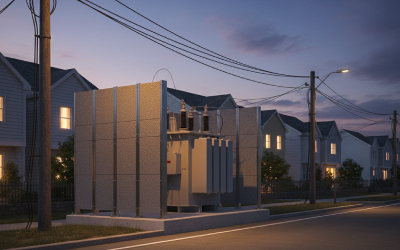
For low-noise transformers in hospitals, tunnels, or buildings:
Joint design is then less of a “yes/no” and more about how carefully you control induction, step geometry, clamp pressure, and vibration paths together.
If your spec just says “step-lap core,” you’re leaving performance on the table. The manufacturing team will fill in the blanks in ways you may not like.
Consider tightening these items in your drawings / RFQs:
If you’re buying lamination stacks or finished cores, you can still keep joint behaviour under control by how you test and review data.
For each new joint style or supplier, it’s worth doing at least one structured comparison:
Over a few batches, the pattern in this data will tell you more about joint design quality than any brochure.
Some practical wording ideas (adapt them to your format):
This is the part where a lamination-focused supplier is useful: once you show that you care about the joint details, you usually get better process control for free, because now it matters to the relationship.
No. With good cutting and stacking, step-lap usually gives lower no-load loss and magnetizing current for the same steel and geometry.
But sloppy patterns, poor burr control or large gaps can erase that advantage. In extreme cases, a badly executed step-lap can even lose to a careful butt-lap.
Because the story isn’t only about the joint type:
Different joint geometries change harmonic content of the exciting current.
A butt-lap core can show lower RMS current yet worse harmonic distortion, depending on how the flux and gaps line up.
If you only look at RMS, you might mis-judge how “hard” the steel is being driven.
For most stacked 3-phase cores:
5–7 steps is a common and practical range.
Below 3 steps, the benefit over a simple lap is small.
Above 8 steps, process complexity and scrap usually climb faster than loss reduction.
The exact number should relate to core size, flux level, and what your cutting line can hold consistently.
Yes, but the sensitivity shifts:
Amorphous strip already has low loss; joint geometry still affects local saturation and noise.
The material is more brittle, so step patterns and cutting tolerance need even tighter control to avoid chipping and gaps.
If you’re going amorphous and chasing every watt, joint design is not optional.
Sometimes.
If the window and overall core cross-section stay the same, many designs can be cut as step-lap within the existing tank.
But lap length and joint position may shift, which can alter lead routing and clamping hardware.
A quick feasibility check with your lamination supplier, plus a prototype loss/noise test, is the safe path.
Three quick checks:
Ask for joint photos of an assembled core showing visible steps at the corners.
Request core loss and magnetizing current data at at least two induction levels.
Compare sound level of one step-lap and one butt-lap core of similar rating in the same test bay.
If all three line up with expected patterns, the step-lap claim is probably backed by real process control.
Bottom line: Joint design is not a decorative detail on a lamination drawing. Butt-lap vs step-lap changes how your lamination stack trades steel grade, cutting tolerance, watts and decibels. Once you decide which side of that trade you’re on for each product family, it becomes much easier to write specs that suppliers can actually hit—and to read test reports with a more critical eye.