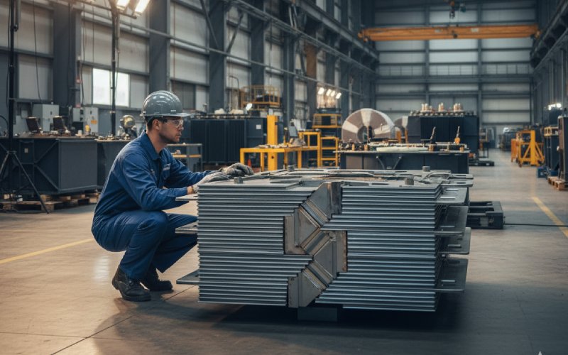
Let Sino's Lamination Stacks Empower Your Project!
To speed up your project, you can label Lamination Stacks with details such as tolerance, material, surface finish, whether or not oxidized insulation is required, quantity, and more.
If you only want the practical shortcut: 0.23 mm is for squeezing losses and labels, 0.27 mm is the everyday workhorse, 0.30 mm is the cost-driven and production-friendly choice. The right answer for you is usually hidden in loss capitalization numbers, factory capability, and how serious your customer is about efficiency, not in marketing names for steel.
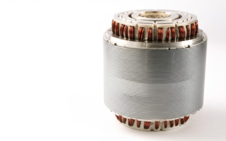
Modern grain-oriented electrical steels are produced in a small set of nominal thicknesses: 0.18, 0.23, 0.27, 0.30 and 0.35 mm in most catalogues. In practice, power and distribution transformers settle on 0.23, 0.27 and 0.30 mm as the standard options, sold under familiar M3, M4 and M5 style grades.
You already know why thinner laminations exist. Eddy current loss scales roughly with thickness squared at a given flux density, so cutting thickness from 0.30 mm to 0.23 mm is not a cosmetic tweak. At the same time, everyone who has actually tried to slit, stack and clamp 0.23 mm Hi-B on a tired line knows it is not free performance.
So the real question is not “which one is best”. It is “which compromise is least annoying for this project”.
Take one representative data set for conventional GOES. A supplier of grain-oriented sheets lists typical core losses at 1.7 T and 50 Hz around 0.9 W/kg for M3 0.23 mm, 1.12 W/kg for M4 0.27 mm, and 1.3 W/kg for M5 0.30 mm. These are not universal numbers, but they are a fair picture of what “normal” coils look like today.
From that one table you can already see the main pattern.
A switch from 0.30 mm to 0.27 mm drops loss by roughly fourteen percent at the same flux density. Moving all the way to 0.23 mm gets you on the order of thirty percent lower loss compared with 0.30 mm. The trend is confirmed in academic work that compares 0.18, 0.23, 0.27 and 0.30 mm oriented steels and finds noticeable differences in core loss and magnetizing current even within this narrow range.
Finite-element and test-based studies on prototype transformers tell the same story, with core losses shifting significantly as the lamination thickness and material grade change between 0.23, 0.27, 0.30 and 0.35 mm sets. So the numbers are real, not brochure optimism.
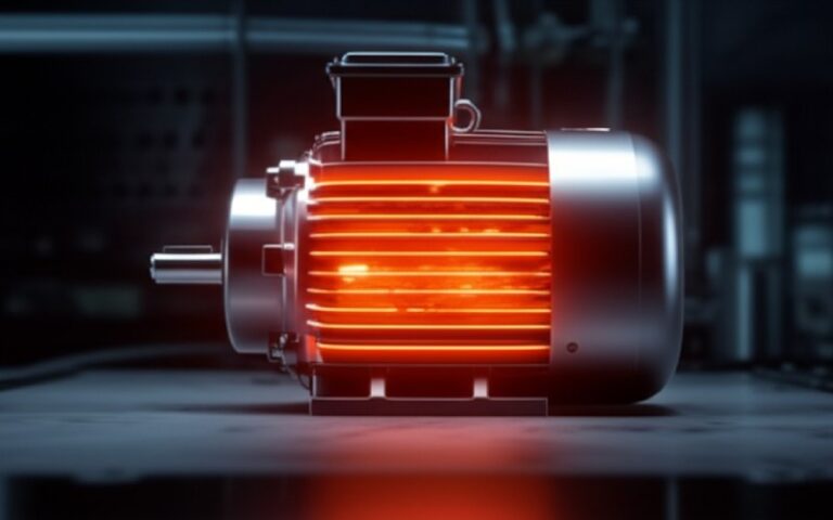
Of course, the moment you go thinner you pay somewhere else. More laminations for the same net cross-section, more insulation layers, more cutting time, more chances for burrs and thickness variation to create local gaps and extra loss. Field reports and process notes from manufacturers keep complaining about how small thickness variation or inaccurate angles already hurt losses and noise.
So there is a three-way trade: loss, manufacturability, and cost.
Here is a compact comparison using typical commercial data and what most factories see on the shop floor. The loss values are indicative, not guarantees, but the ratios are representative.
| Thickness (mm) | Typical CRGO grade label | Approx. core loss at 1.7 T, 50 Hz (W/kg) | Relative loss vs 0.30 mm | Typical use focus | Why designers pick it |
|---|---|---|---|---|---|
| 0.23 | M3 or Hi-B/domain refined variants | About 0.9 W/kg for standard M3; advanced domain-refined grades are quoted down to about 0.85 W/kg. | Roughly 30 percent lower than typical 0.30 mm M5 at the same flux density. | High-efficiency distribution transformers, compact designs, premium power transformers, low-noise units. | To meet aggressive loss caps or star labels without oversizing the core; to shrink tank size and oil volume; to cut audible noise when combined with good geometry and processing. |
| 0.27 | M4 and similar | Around 1.1–1.15 W/kg in common spec tables. | Roughly 10–15 percent lower than 0.30 mm M5. | General-purpose distribution and medium power transformers where efficiency and price both matter. | To get most of the loss reduction benefits without over-complicating manufacturing; to stay inside familiar cost and supply chains. |
| 0.30 | M5 and similar | Around 1.3 W/kg for many catalogues at 1.7 T, 50 Hz. | Baseline. | Cost-sensitive units, older designs carried forward, some higher-rating transformers where other losses dominate. | To simplify handling and stacking, make use of slightly higher stacking factor, and keep steel cost per kilogram lower where energy tariffs or regulations are less strict. |
This is the physics summary. The rest of the article is about when these numbers actually change your drawing.
You typically justify 0.23 mm when one of three things is true.
First, when no-load loss is monetized heavily. Many utility tenders and energy-efficiency schemes essentially put a price on every watt of core loss through loss capitalization formulas. If the loss capitalization factor is high, the present value of a twenty or thirty percent reduction in no-load loss is often greater than the extra steel and processing cost. The calculation is not elegant, but it is usually decisive.
Second, when you are chasing compactness. Thinner laminations let you tolerate a bit more flux density for the same loss target in many grades, which means a smaller cross-section for the same transformer rating. That shrinks the tank, reduces oil volume, and sometimes knocks one or two centimeters off each dimension. For urban distribution transformers, pad-mounted units or renewables where footprint is constrained, this is tangible.
Third, when you are fighting noise limits. Several mills offer domain-refined 0.23 and 0.27 mm products using mechanical or etched groove treatments to cut magnetostriction and iron loss without badly affecting other properties. Low-noise product series around 0.23 mm thickness are widely marketed for transformers with strict sound-level clauses. If your noise budget is already tight, combining step-lap joints, good clamping, and 0.23 mm Hi-B is a straightforward way to buy margin.
The price you pay is on the factory side. Thinner CRGO is more sensitive to handling damage and bending, and the process window for cutting, stacking and annealing gets narrower as thickness drops to 0.23 mm and below. Industry notes emphasize that these sheets must not be bent sharply, and that even modest thickness variation within a strip step gives trouble both in stacking and in final losses.
You trade easier design targets for more demanding production control.
There is a reason so many manufacturers describe 0.27 mm M4 as the balance point between efficiency and cost. If you look at the earlier loss table, 0.27 mm recovers most of the benefit of going thinner compared with 0.30 mm while avoiding the worst of the production pain that 0.23 mm brings.
In a typical 50 or 60 Hz distribution transformer, the step from 0.30 to 0.27 mm often saves on the order of ten to fifteen percent core loss for the same flux density. That shows up as a cleaner path to mid-level efficiency classes without a large change in design philosophy. You rarely need to redraw the whole core window; you just push the flux a little higher or accept lower losses at the same induction.
On the shop floor, 0.27 mm still behaves like familiar steel. Stacking factor is slightly lower than 0.30 mm but not dramatically so, and bending strength and edge durability are easier to manage than with 0.23 mm. For factories that rely on a mix of automated and manual stacking, that mechanical margin matters more than it seems on paper.
In short, if your customer expects decent but not extreme efficiency and your plant is tuned around M4 coils, 0.27 mm is usually the least risky answer.
It is tempting to think 0.30 mm is “old” and should be retired, but there are situations where it is still rational.
First, where capitalized energy costs are low. Some industrial or regional grids still do not put a strong price on every extra watt of no-load loss. If the loss capitalization factor is modest and tariffs are low, the payback time for stepping down to 0.27 or 0.23 mm can stretch beyond the asset owner’s comfort.
Second, where your design runs at conservative flux density. The core loss numbers quoted in catalogues, such as around 1.3 W/kg at 1.7 T for 0.30 mm, assume relatively high induction. If you are running at 1.5 T or lower, and your load losses dominate, the relative importance of reducing core loss shrinks.
Third, in some higher-MVA units, material flow and winding complexity dominate the economics. A slightly thicker lamination gives you a bit higher stacking factor and is more forgiving of small assembly errors. That can outweigh the pure loss benefit in a real factory with finite quality control.
So 0.30 mm is not only for legacy drawings. It is still useful when you deliberately trade a little extra iron loss for robustness and simplicity.
Take a very simple example just to frame orders of magnitude. Suppose a transformer core uses about 400 kg of CRGO. This is in the ballpark for a mid-size distribution unit, but the method matters more than the exact rating.
Using the indicative figures earlier, 0.30 mm M5 at 1.7 T might give about 1.3 W/kg; 0.27 mm M4 might be around 1.12 W/kg; 0.23 mm M3 around 0.9 W/kg.
At the same flux density, that means:
The 0.30 mm core burns roughly 520 W of no-load core loss. The 0.27 mm core burns about 448 W. The 0.23 mm core burns about 360 W.
So moving from 0.30 to 0.27 mm saves around 72 W, and moving from 0.30 to 0.23 mm saves around 160 W.
A transformer that runs all day, every day, consumes 8,760 hours of no-load energy per year. Those differences translate to about 631 kWh and 1,402 kWh of energy saved per year relative to the 0.30 mm design.
If the owner values energy at, say, 0.10 currency units per kWh, then the 0.27 mm option saves roughly 63 units per year, and the 0.23 mm option about 140 units per year. Over a 10-year horizon, even ignoring discounting, that turns into hundreds to more than a thousand units of value. Steel price differentials between 0.23, 0.27 and 0.30 mm coils, as seen across commercial offers, are often well below that per transformer.
Real projects involve more terms: exact flux, duty cycle, load losses, temperature limits. Still, a very rough check like this usually confirms that 0.23 mm looks attractive wherever energy is priced seriously.
Thickness is not the only handle you can pull, and sometimes it is not the first one you should move.
Domain refinement and Hi-B processing can cut loss significantly at the same thickness by breaking up magnetic domains using mechanical grooves or etched patterns. JFE’s JGSD products, for example, use linear grooves on 0.23 and 0.27 mm sheet to reduce iron loss without strongly hurting magnetostriction. Mills across Asia and Europe offer similar “low-loss” variants that can nudge you closer to a target without changing the lamination gauge.
Geometric details also keep surprising designers. Step-lap joints, better control of mitre angles, and tighter tolerances on lamination size and burrs reduce both core losses and acoustic noise. Recent notes from core manufacturers point out that even small deviations in lamination size or burr thickness create uneven gaps and increase noise and loss.
Material thickness variation across a strip, sloppy cutting angles, and poor clamping easily eat the theoretical gain of going from 0.30 to 0.27 mm. That is why some factories first invest in better decoiling, cutting, stress-relief annealing and stacking processes before they move aggressively to 0.23 mm Hi-B grades.
So a good question to ask, before changing gauge, is whether your existing line is actually delivering the performance your datasheets assume.
You will have your own rules of thumb, but the pattern below matches what many design teams end up using once the spreadsheets and supplier calls are done.
For small distribution transformers where regulatory loss caps and energy labels are tight, and where units sit energized for decades, 0.23 mm tends to dominate. The lifetime cost of core loss is so influential that even a modest improvement justifies extra material and process care.
For the mid-range, from a few hundred kVA up to a few MVA in typical 11 or 33 kV grids, 0.27 mm is often the practical standard. It lets you clear most tender requirements and BEE or Ecodesign-style efficiency levels while keeping the factory workflow close to traditional patterns.
For large power transformers, special industrial transformers, or projects in markets where energy pricing and regulation are less aggressive, 0.27 and 0.30 mm coexist. You see 0.27 mm where customers explicitly ask for high efficiency, and 0.30 mm where design teams prioritize proven processes, mechanical margins and cost per unit over small gains in no-load loss.
This is not a rigid map. It is a way to reduce argument time inside your own team.
Material availability still matters. Global suppliers stock different combinations of grade and thickness, often quoting standard sets like M3 0.23 mm, M4 0.27 mm and M5 0.30 mm with minimum order quantities and width ranges tuned to transformer makers. If your volume is modest, you may find that true premium 0.23 mm grades are only economical in larger lots, whereas 0.27 and 0.30 mm have more flexible terms.
Some catalogues also highlight different thickness tolerance bands for the 0.23–0.27 mm range compared with 0.30–0.35 mm. That is not just a quality line on paper. Tighter thickness control directly influences stacking behavior and final core losses.
Finally, your existing tooling can subtly limit you. Cut-to-length lines, step-lap tooling, and annealing ovens were often sized around a particular range of widths and thicknesses. Sliding from 0.30 to 0.27 mm is usually safe. Jumping to 0.23 mm sometimes exposes weaknesses in flattening, cutting and stacking that were never obvious before.
So if you are writing a specification for multiple suppliers, it is worth talking to them candidly about what thicknesses they can genuinely process well at your required volume, not just what appears in the brochure.
If you strip away the marketing, the choice between 0.23, 0.27 and 0.30 mm CRGO laminations is mostly about cash flows, process stability and risk.
When the customer pays for every watt saved and you trust your factory control, 0.23 mm makes a lot of sense. It drops core loss substantially, helps noise and footprint, and aligns with modern high-efficiency expectations.
When you want good efficiency without complicating life on the shop floor, 0.27 mm is a very safe center point. Many utilities and OEMs quietly standardize around it for exactly that reason.
When your priority is predictable manufacturing, conservative operation and minimum upfront cost in a forgiving regulatory environment, 0.30 mm still has a valid place.
Pick the lamination thickness that matches not only your magnetic design but also your processes, suppliers and customer’s time horizon. The steel itself is only half the story; the way you cut, stack and clamp it decides whether the theoretical benefit ever leaves the datasheet.