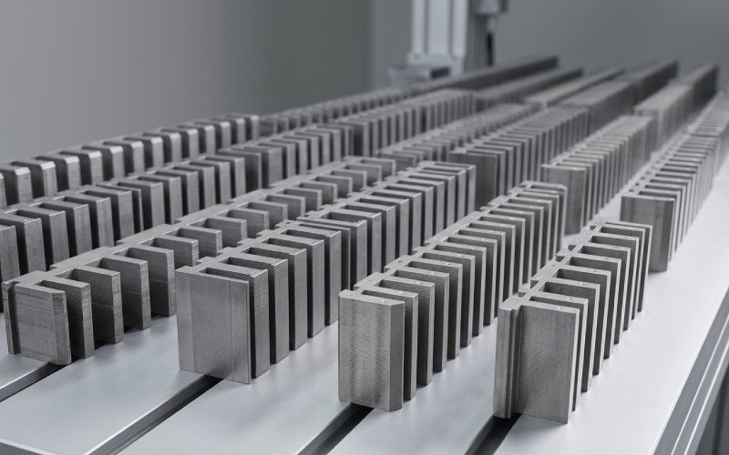
Let Sino's Lamination Stacks Empower Your Project!
To speed up your project, you can label Lamination Stacks with details such as tolerance, material, surface finish, whether or not oxidized insulation is required, quantity, and more.
CRGO datasheets usually give you a couple of hard points:
Sometimes only one of them. The mill guarantees one induction point; everything else on the curve is “typical”.
The problem: you never run the core exactly at the guarantee point. You run at “whatever flux density the design and tolerances decide”, plus over-flux events, plus noise limits, plus your stacking reality.
So treat the P–B curve like this:
A typical CRGO data set at 50 Hz, from a classic GOES brochure, looks like this for 0.23 and 0.27 mm grades (M-3 and M-4):
| Flux density B (T) | M-3, 0.23 mm (W/kg) | M-4, 0.27 mm (W/kg) |
|---|---|---|
| 1.0 | 0.283 | 0.338 |
| 1.3 | 0.477 | 0.575 |
| 1.5 | 0.658 | 0.792 |
| 1.7 | 1.002 | 1.144 |
| 1.8 | 1.353 | 1.386 |
Three quiet points that engineers know, but purchasing sometimes doesn’t:
So when somebody says “this is M3, 0.23 mm”, that’s not enough. You still need the curve, or at least two points on it.
You can pick CRGO grade and lamination thickness in many ways. The most boring one works best:
Fix a realistic operating flux density band, then buy steel that behaves acceptably inside that band.
Approximate working windows at 50 Hz, for CRGO cores in oil, assuming ONAN/ONAF transformers and decent cooling margins:
These are not rulebook values. They’re “numbers people quietly use” because they survive field experience and grid over-voltage habits.
Once you agree this window internally, grade selection gets much less noisy.
Let’s use the M-3 / M-4 table as a simple model and assume your design sits at ~1.55 T in steady operation.
Engineers know loss vs B is not a perfect power law, but between 1.3–1.7 T it behaves “roughly” like:
P(B) ≈ P_ref · (B / B_ref)^n, with n somewhere around 1.6–2.0 depending on steel and frequency.
Now line up some scenarios at 50 Hz:
For a 2,000 kg core, that’s:
Same steel, same lamination stacks. Only B moves.
So for a purchasing engineer, P1.5/50 and P1.7/50 are not just catalogue numbers – they are a quick way to sketch out exactly how much penalty you pay if the designer raises the flux 0.1 T to save copper.
Most Hi-B or laser-scribed grades sit roughly one step “better” on the loss curve than conventional CRGO at the same thickness. Typical P1.7/50 values around 0.7–0.9 W/kg at 0.23–0.30 mm are common in modern catalogues.
That doesn’t automatically mean you should buy them.
Think in three quick passes:
In short: pay for Hi-B when you either:
Otherwise, a well-specified conventional CRGO (with explicit W/kg limits) plus a sensible B window is usually enough.
Plenty of blog posts already list thickness vs loss qualitatively. The usual story still holds: thinner strip, lower eddy losses, better at higher flux and frequency – and higher processing cost.
A practical way to think about it:
So rather than “0.23 is premium, 0.27 is standard, 0.30 is budget”, phrase it this way:
“For a given B window and loss target, what thickness gives you the cheapest total package when you include copper, tank, and penalties on kWh?”
Many modern guides now explicitly show those trade-offs using total owning cost curves for distribution transformers.
Data sheets are measured on carefully prepared strips. Your core is not a strip.
Three correction factors matter more than the rest:
Spacemat’s GOES brochure shows typical lamination factors for CRGO around 95–97% at 50 psi, depending on thickness and coating.
That means:
Nippon Steel’s ORIENTCORE HI-B data gives a neat comparison:
Corner joints, flux rotation, local saturation in T-joints, air gaps at overlaps – they all add extra watts that never show in the bare strip test.
For conventional CRGO wound or stacked cores, building factors between about 1.1 and 1.3 are common depending on design and lap style.
Counter-intuitive, but worth remembering: for GOES, core loss measured at 85 °C is often slightly lower than at 25 °C because resistivity increases with temperature and reduces eddy currents. Spacemat’s table shows W(85 °C)/W(25 °C) hovering around 0.95–0.98 across 1.0–1.7 T.
So if your spec quotes P1.7/50 “at 65 °C” and the datasheet quotes “at 20–25 °C”, losses will not scale in the obvious way. You still validate on the mill’s stated test condition.
Here’s a simple workflow that turns all the above into a defendable RFQ.
From the transformer designer:
This lets you estimate:
For example, suppose:
Assume:
Then the strip level target at 1.6 T becomes roughly:
Core loss per kg (strip) ≈ 1.7 kW / (2000 kg × 1.18) ≈ 0.72 W/kg at 1.6 T
From the M-3 table, 0.23 mm gives ~0.79 W/kg at 1.6 T, which is a bit higher. That tells you:
This is the kind of arithmetic that should show up in the design notes, not just in someone’s head.
Instead of “CRGO M3, 0.23 mm”, write something like:
CRGO lamination stacks, 0.23 mm, grade equivalent to M108-23 or better.
- P1.5/50 ≤ 0.70 W/kg, guaranteed as per IEC 60404-2 / JIS C 2550-1
- P1.7/50 ≤ 1.05 W/kg, same test conditions
- B50 ≥ 1.88 T (5000 A/m)
- Coating: C-5 equivalent, suitable for stress-relief annealing at 800 °C
- Lamination factor at 50 psi ≥ 96%
Numbers above are indicative, but this style of sentence is what keeps both sides honest.
Don’t rely only on catalogue summary lines.
Request from your lamination supplier:
If they cannot supply the curve, they at least should tell you which mill datasheet they are actually buying from.
A few situations where the nice Epstein-frame curve misleads you:
When any of these show up, you either:

For each new transformer design or major RFQ, make sure you can answer, on one page:
If any of these boxes is empty, the core loss vs flux density curve will usually fill it in for you later, in the form of unexpected watts.
A: For conventional CRGO, mills often guarantee only one point, typically P1.5/50, while Hi-B families use P1.7/50. If your design ever runs beyond 1.6 T, having both numbers (or a small table over 1.3–1.7 T) is safer. It gives you a better feel for how steep the curve is near your maximum B.
A: Building factors between about 1.1 and 1.3 are normal for stacked CRGO cores, depending on joints and flux distribution. If you design assuming “material loss = transformer loss”, you are optimistic by at least 10–20%.
A: Roughly, P ∝ f for the hysteresis-dominated range and P ∝ f² for pure eddy currents, but real GOES mixes both plus excess loss. Many datasheets give both P1.5/50 and P1.5/60; if not, use the mill’s recommended conversion or standard guidance (for example, some standards note that 50 Hz losses at 1.5 T are roughly 0.79× the 60 Hz value for similar steel). For critical orders, insist on 50 Hz numbers if that’s your operating frequency.
A: The old M-labels are still common on drawings and in conversations because they encode a fuzzy thickness and loss window. Modern IEC/EN/JIS datasheets, though, are organised around P1.7/50 bands and thickness rows, so grade codes like “M125-27” tell you more precisely what you’re getting. Best practice: keep the M-label for quick communication, but lock the purchase around explicit W/kg limits and thickness.
A: Not very close. You still have:
Lot-to-lot scatter,
Building factor,
Measurement tolerances across different labs.
Leaving at least 10–15% margin below the guaranteed maximum at the reference induction is common. Some suppliers even publish their typical loss window vs guaranteed limit and the lot-to-lot tolerance (for example ±0.03 W/kg on P1.5/50).
A: At the same B and frequency, yes – but design is rarely “at the same B”. The choice of thickness shifts your optimal B window; a design using 0.23 mm may run at slightly higher B than a 0.27 mm design for the same total loss target. On top of that, tooling cost, punching speed, and yield often favour 0.27 mm. So you compare total cost at a fixed loss target, not thickness in isolation.
A: Many transformer specifications now require W/kg to be declared at 1.3, 1.5 and 1.7 T at 50 Hz and a defined temperature. This gives you a clearer picture of curve shape, especially if you run relatively low B but want to understand behaviour under over-flux. It also makes it harder for a supplier to “optimise” only one point on the curve.