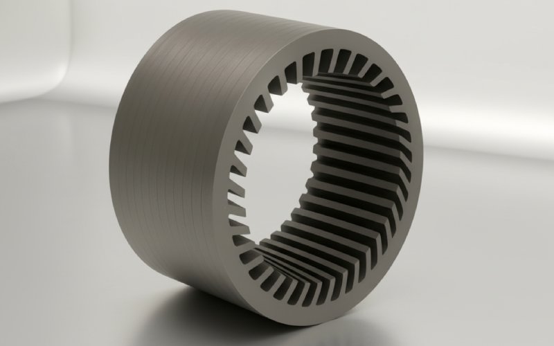
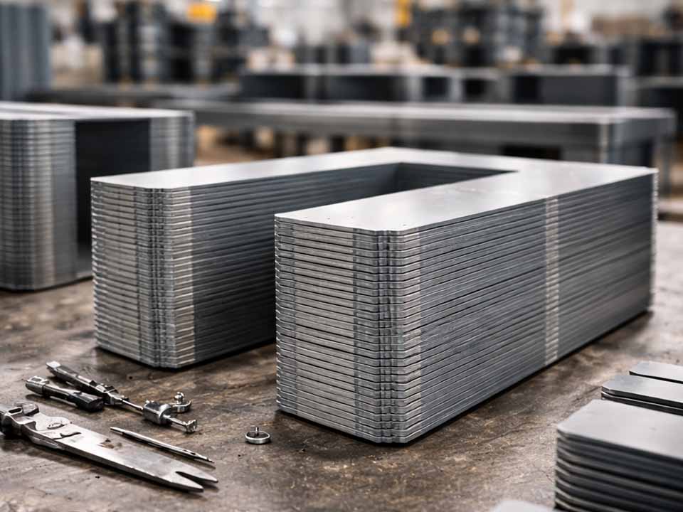
Let Sino's Lamination Stacks Empower Your Project!
To speed up your project, you can label Lamination Stacks with details such as tolerance, material, surface finish, whether or not oxidized insulation is required, quantity, and more.
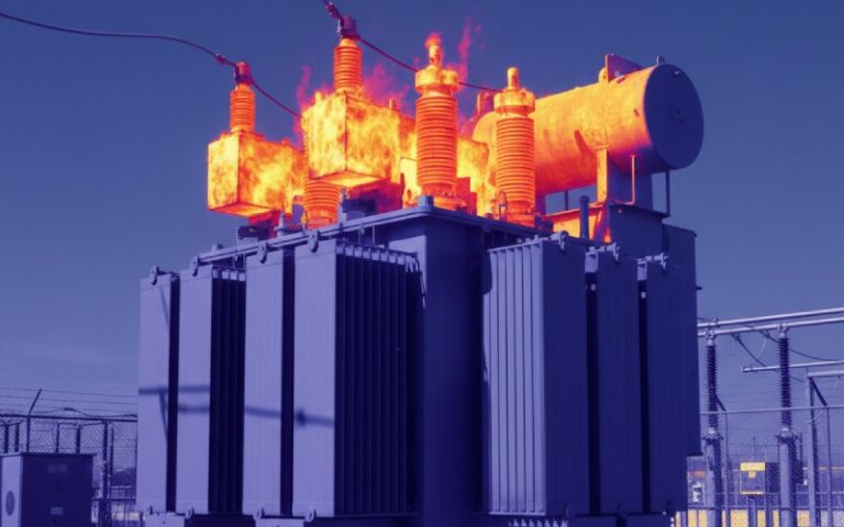
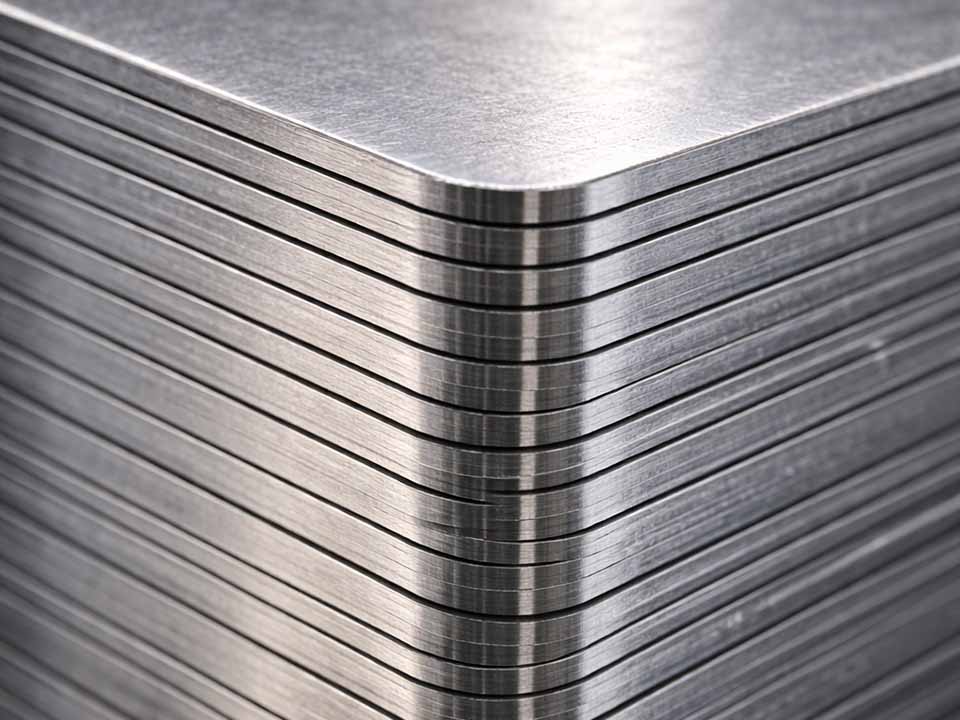
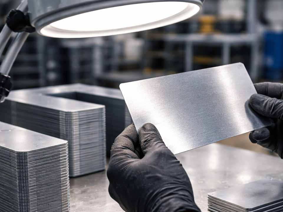
If you’ve ever compared two “identical” CRGO (cold-rolled grain-oriented) steel quotes and wondered why core loss, noise, or rework risk doesn’t line up with the datasheet… the answer is often hiding in a few characters: the insulation coating class. Coatings are the invisible engineering layer between laminations—thin enough to ignore in a drawing, but important enough to change watts, heat, and long-term reliability in the field.
CRGO is special because its “baseline coating” is not just a paint—it’s closely tied to the steel’s final high-temperature processing. Many grain-oriented electrical steels are supplied with a thin inorganic coating on the glass film layer that forms during annealing, typically only a few microns thick, balancing electrical resistance and stacking factor.
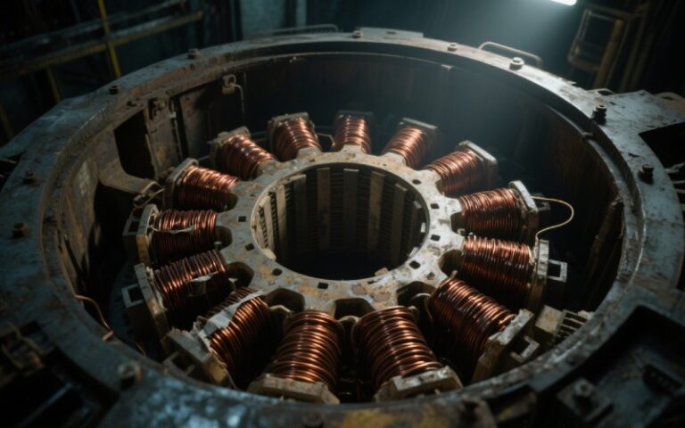
A lot of transformer engineers casually call the CRGO surface “coated,” but with grain-oriented steel the key starting point is the C-2 style mill glass / glass film: an inorganic layer formed during high-temperature annealing from the reaction of the annealing separator and the steel surface.
Some producers describe grain-oriented electrical steel as having two coating layers—a base layer and an additional coating—because the surface system can be engineered for insulation, corrosion resistance, and mechanical tension.
The most widely referenced “C-classes” come from ASTM A976, which classifies coatings by composition, relative insulating ability, and application guidance. Below is a practical, CRGO-focused interpretation of what these classes mean—especially when your end product is a transformer core.
| ASTM class | What it is (plain-English) | Heat / anneal behavior (typical) | Where it shows up most | What it means for CRGO |
|---|---|---|---|---|
| C-0 | Natural oxide formed during mill processing | Withstands normal stress-relief anneal; insulation depends on atmosphere | Small cores, basic needs | Rarely the “headline” in CRGO buying; more common as a baseline on other steels |
| C-1 | User-formed oxide created by furnace atmosphere at end of heat treat | Depends on your process; “formed” by the user | Various applications | Not the typical CRGO transformer default, but relevant if you rely on user heat-treat atmospheres |
| C-2 | Inorganic magnesium-silicate “mill glass / glass film” on GO | Withstands normal stress-relief; abrasive | Wound distribution transformers; GO steel | The classic CRGO foundation; great thermal durability, but abrasive and process-sensitive |
| C-3 | Organic varnish/enamel cured by heating | Not for typical stress-relief anneal; suitable up to ~180 °C | Fully processed non-oriented (motors), stamped parts | Usually not the go-to for CRGO transformer cores unless you’re doing a specialized secondary coating approach |
| C-4 | Chemically treated/phosphated + cured | Withstands normal stress-relief, but insulation may reduce | Moderate insulation needs | Can appear as a “more engineered” inorganic coating when you need moderate resistivity plus heat tolerance |
| C-5 | Inorganic/mostly inorganic (often phosphate/chromate/silicate) with fillers for higher insulation; can be applied over C-2 | Can withstand stress-relief up to ~840 °C in neutral/slightly reducing; may reduce resistivity after anneal | High surface resistivity needs; can be used in air-cooled or oil-immersed cores | This is the common “upgrade path” for CRGO when you need extra interlaminar resistance—especially for sheared laminations in power transformers |
| C-6 | Organic coating with inorganic fillers; cured by heating | Generally not considered stress-relief capable (some modern variants exist) | Fully processed non-oriented; devices needing strong insulation | Usually more motor-centric than transformer-centric; evaluate carefully if someone suggests it for CRGO |
What’s easy to miss is that the ASTM standard warns that product names in the market may resemble these classes, and you should confirm a coating truly conforms to the classification if it’s being sold under a similar label.
Here’s the deeper way to think about it: your coating isn’t just insulation—it’s your manufacturing interface and your loss-control system at the same time. You choose it by asking: Where will current try to sneak across sheets? Where will my process damage insulation? And which thermal steps will punish the film?
A very common pattern in transformer work is:
Many “overview” articles stop at definitions. In practice, the coating problems that cost you money don’t announce themselves as “wrong class”—they show up as noisy scrap trends, inconsistent core loss, or unexplained hot spots.
If you want to surpass competitors, don’t just ask “what class is it?” Ask: how do we measure and control it? International standards exist specifically for this.
Standardized methods describe how to measure surface insulation resistance of electrical steel strip/sheet (useful for manufacturing and quality control of insulation coatings). Other methods define how to assess the thermal endurance of surface insulation coatings on electrical steel.
A strong coating conversation with a mill or service center sounds less like “C-2 vs C-5” and more like “system behavior under my real constraints.”
It’s tempting to treat coating class as procurement paperwork. But in transformer cores, the coating is part of the electromagnetic circuit, because it shapes how and where unwanted currents can flow. The best-performing CRGO designs tend to win not only on steel grade and core geometry, but on aligning the entire stack—cut quality, coating system, anneal steps, and QA measurement—so the insulation you paid for still exists after your process is done.
If you’d like, tell me what transformer type you build (distribution vs power, wound vs stacked/sheared, any stress-relief anneal), and I’ll translate this into a one-page internal coating selection guide your team can use for RFQs and incoming inspection.
Internal links list source: