Let Sino's Lamination Stacks Empower Your Project!
To speed up your project, you can label Lamination Stacks with details such as tolerance, material, surface finish, whether or not oxidized insulation is required, quantity, and more.
CRGO lamination is simply the practice of cutting, coating and stacking grain-oriented electrical steel so that a transformer core moves flux in one preferred direction with as little wasted energy as your budget, tooling and supply chain will realistically allow.
Cold Rolled Grain Oriented (CRGO) steel is just electrical steel whose grains are lined up along the rolling direction, and a “CRGO lamination” is one piece of that steel, punched or laser-cut, individually insulated, then stacked into a core so the flux mostly follows that rolling direction. That is all the phrase means in principle: oriented material plus geometry plus process, working together to keep core loss and magnetizing current low in power and distribution transformers.
Of course, reality is messier than that one line.
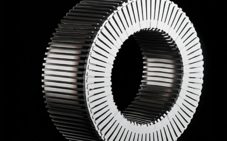
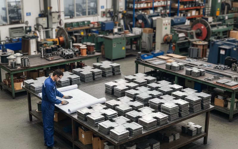
By the time you see a neat stack of E, I, C, or step-lap plates in a transformer shop, that CRGO has already gone through several filters: mill processing, slitting, cutting, insulating, then assembly. Every one of those steps can either respect the grain orientation or quietly destroy its advantage.
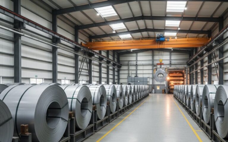
Mills supply CRGO as coils with a specified thickness, grade and coating. Common thicknesses are around 0.23 mm, 0.27 mm and 0.30 mm, each tied to a loss target at 1.5 or 1.7 T and 50 Hz. Coils are slit into narrow strips and then converted into laminations by stamping or laser cutting, followed by some combination of stress-relief annealing and stacking.
On drawings and datasheets this looks simple: “CRGO M4, 0.27 mm, coating type X, max W/kg at 1.7 T”. In the workshop, it is a fight against burr height, misalignment, coating damage, and people who think it is fine to bend laminations like mild steel. CRGO lamination is less about the acronym and more about how much of the mill’s carefully produced texture actually survives your process.
If you already know the official theory, you know that in CRGO the grains are oriented so flux prefers the rolling direction. Spec sheets show core-loss numbers for flat Epstein strips, perfectly cut along that direction. For example, a typical M4-type oriented steel around 0.27 mm thickness may be specified with core loss near or below about 1.2–1.3 W/kg at 1.7 T, 50 Hz. High-grade and Hi-B type steels drive those numbers closer to 0.7–0.9 W/kg depending on thickness.
Once you cut laminations and build a real three-phase core, flux does not politely remain at 0°. It bends at the corners, enters joints obliquely, crosses regions where the steel is effectively off-angle relative to rolling direction. Nippon Steel’s Hi-B data, for instance, shows how different joint patterns produce measurable differences in local and total core loss even with the same material.
So the real job of CRGO lamination is not just “low loss steel”. It is arranging plates, joints and gaps so that the flux path spends as much of its journey as possible in that preferred direction, at a flux density that the grade can handle without sharp rises in loss or noise.
The mill side is mostly fixed for you: primary rolling, decarburizing, primary recrystallization and then secondary recrystallization to grow the large Goss-oriented grains, followed by coating and temper rolling. That is where the “grain oriented” part is born.
On the lamination side, the important stages are narrower and more brutal:
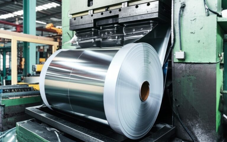
The strip gets cut. If you stamp, the tools introduce mechanical stress and burrs along the cut edge; if you use laser cutting, you trade mechanical deformation for thermal impact and potential edge oxidation. The Banmore manufacturing article walks through this but from a marketing angle; in practice, the choice of cutting method is a trade between speed, cost, edge quality and how much post-cut annealing you are willing to pay for.
Each lamination is coated. Coatings are thin inorganic or hybrid layers designed to keep laminations electrically isolated from each other, to control interlaminar resistance and provide some sticking friction during stacking. Remove or scratch them too much and eddy currents flow freely across the stack; leave them uneven and you get hot zones and unpredictable lamination factor.
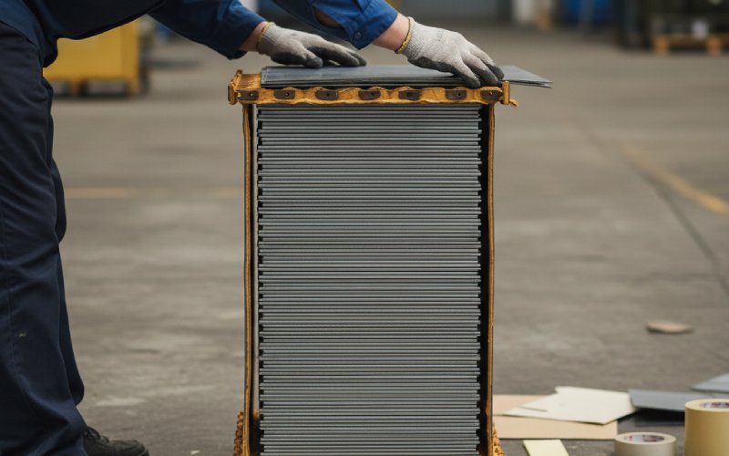
Finally, laminations are stacked into a core: step-lap, mitered, butt-joint, wound, stacked, sometimes annealed again. Every step either preserves the mill’s microstructure or loads it with extra stress and local misorientation. Manufacturing guides often list seven or eight neat steps; the real-world version is a loop of cutting, checking, reworking, and adjusting stacking patterns until the assembled core loss test lands where you promised it would.
When designers say “use CRGO laminations”, they are actually tuning several independent knobs. They just happen to live behind one phrase.
The first knob is grade and thickness. For many dry-type and oil-filled distribution transformers you will see grain-oriented silicon steel grades around M3 or M4 with thickness in the 0.23–0.30 mm band. Thinner gauges reduce eddy currents and loss but increase material handling effort, cost, and the number of laminations in each stack. For high-end power transformers or compact designs, Hi-B type grades give lower loss at the same flux density, but they are more sensitive to cutting and stress. Choosing between “regular” CRGO and Hi-B is not a philosophical discussion; it is usually a spreadsheet of no-load loss cost versus extra steel and processing cost over the life of the transformer.
The second knob is joint and cut pattern. Articles on CRGO lamination types talk about mitered cuts, diamond cuts, step-lap arrangements, and various notch patterns used to align limbs and yokes. From an engineering point of view this boils down to how gently you change the flux direction at joints, and how often you force flux to pass through 90° or close to it. Step-lap cores with mitered joints spread the flux turn, keep local flux density peaks lower, and usually give better no-load loss and lower noise than simpler butt-joints, at the cost of more complex cutting and stacking.
The third knob is coating and lamination factor. Even a very low core-loss steel will not deliver its rated performance if your lamination factor is poor. Coating thickness, consistency, curing quality and the amount of mechanical damage during handling all end up in that number. Mill data sheets give lamination factor numbers around the mid-90% range; assembled cores rarely hit those ideal values, especially if cutting and stacking are not tightly controlled.
The fourth knob is stress management. Every punch, clamp and bend introduces residual stress; CRGO’s magnetic properties are extremely sensitive to that. This is why some manufacturers emphasize a final stress-relief anneal of the assembled core, especially for high-voltage or high-flux designs. Skip that step, and you are effectively paying Hi-B prices for something behaving closer to ordinary grades.
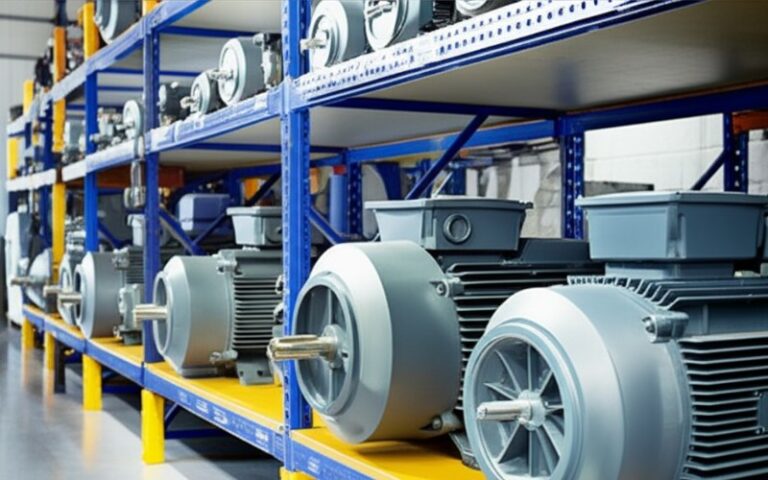
In many blogs the comparison with CRNO or amorphous metal is addressed in vague terms. You already know the basic story: grain-oriented silicon steel for transformer cores, non-oriented for rotating machines, amorphous for very low loss. The more useful view is to line up what this means numerically for laminations.
Based on recent dry-type transformer data, typical core-loss ranges at 1.5 T, 50 Hz look roughly like this: CRGO (M3 grade) around 1.0–1.3 W/kg, CRGO Hi-B around 0.7–0.9 W/kg, amorphous metal around 0.2–0.3 W/kg and CRNGO around 2.0–2.5 W/kg. At the same time, amorphous cores use very thin ribbon, typically about 0.025 mm thick, which is roughly one tenth of common silicon-steel lamination thickness. CRGO sheet thickness is more commonly in the 0.23–0.30 mm range, with specific grade tables tying each thickness to a pair of loss values at 1.5 and 1.7 T.
Putting those ideas together gives a more lamination-oriented comparison:
| Core material (typical) | Approx. lamination / ribbon thickness | Typical core loss at 1.5 T, 50 Hz (W/kg) | Usual role in power equipment | Lamination-side remarks |
|---|---|---|---|---|
| CRGO, M3-type oriented silicon steel | 0.23–0.27 mm sheet | About 1.0–1.3 | Standard distribution and many power transformers | Balance of cost, processability and loss; tolerates moderate manufacturing stress if joints and coatings are well controlled. |
| CRGO, Hi-B or premium grades | 0.23–0.27 mm sheet | About 0.7–0.9 | High-efficiency or high-voltage cores | Needs careful cutting, low burr height and often stress-relief annealing to keep the promised loss figures. |
| CRNGO (non-oriented silicon steel) | 0.35–0.50 mm sheet | About 2.0–2.5 | Rotating machines, small transformers | Loss is higher, but properties are more uniform in all directions, helpful for rotating flux patterns. |
| Amorphous metal alloy | ≈0.025 mm ribbon, wound | About 0.2–0.3 | High-efficiency distribution transformers | Extremely low loss but mechanically hard and thin; far more laminations, wound-core technology and different handling methods. |
For someone specifying CRGO laminations, this table says something simple: you are in the middle ground. CRGO laminations will not match amorphous ribbon for no-load loss, but they are easier to cut, stack and clamp into complex core shapes, especially at higher powers and voltages.
Good CRGO lamination is not just about buying high-grade coils. It shows up in small, measurable details.
Burr control comes first. Burr height affects local flux and increases loss around joints. Most serious CRGO handling guidelines set tight limits on acceptable burrs and recommend processes to control them. Tool sharpening schedules, stamping clearance, and de-burring methods end up visible in no-load loss test results.
Cut orientation is next. Many shops still occasionally cut parts at sub-optimal angles to save material. Every degree away from the rolling direction increases loss and magnetizing current, especially in Hi-B grades where the texture is stronger. Mill catalogs and technical brochures show how sharply loss increases once the magnetization direction moves away from the rolling direction, so your nesting and scrap strategy is inherently a magnetic design choice.
Coating integrity is quiet but important. Scratched, over-baked or contaminated coatings reduce interlaminar resistance. In assembled cores this shows up as higher eddy-current loss than predicted by single-sheet measurements. Modern coatings are formulated for high-temperature resistance and good adhesion, yet they are not invincible to aggressive handling, oil contamination or rough stacking.
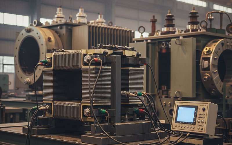
Finally, the stacking pattern itself. Whether you use simple overlapping joints or complex step-lap sequences, the way laminations are arranged at corners decides how close your assembled core comes to the mill’s W/kg numbers. Demonstrations of model transformers with different joint methods show clear differences in both total loss and local hot spots even with identical steel. The material is the same; the lamination strategy is not.
Because you already know the material basics, the real value in a specification is to describe how you expect the laminations to behave, not only what they are made of.
It often helps to state loss requirements for the assembled core, not only for the steel. For example, specifying “core loss of the tanked transformer at rated voltage and frequency shall not exceed X W at Y °C” is stricter than just “CRGO grade 23HP90 or better”, because it forces the lamination process to be part of the guarantee. Grade tables such as those published for BIS/ISI CRGO grades show thickness and max W/kg per grade, and they are a good starting point for setting those numbers.
You can also control lamination quality with simple, testable constraints: maximum burr height, maximum allowed off-angle cutting relative to rolling direction, minimum lamination factor for the assembled core, whether a final stress-relief anneal is mandatory for certain power ratings, which joint patterns are allowed. None of this requires long essays; a few clear lines in the drawing notes often steer manufacturing more than another paragraph of marketing text.
And then there is supply chain reality. Secondary or “oily” CRGO exists and can be attractive for cost reasons, particularly in lower-power or less critical applications. Articles from lamination suppliers explicitly discuss how different lamination types and sheet qualities are chosen for prime versus secondary CRGO. If you allow such material, the specification should say where it is acceptable and what tests must still be met. Otherwise you will get surprises.
So, what is CRGO lamination? It is not only a material type. It is the combination of oriented electrical steel, thickness, coating, cutting method, joint geometry and stress control that decides whether your transformer core actually behaves like the neat W/kg numbers from the mill, or wanders off by tens of percent once assembled.
Once you see it that way, conversations stop being “CRGO versus something else” and become “which lamination choices give the loss, sound level and cost profile we can live with”. That is a far more useful question when you are signing off a real design, not just reading a brochure.