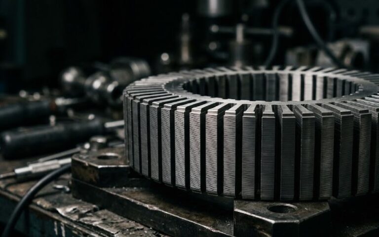
Let Sino's Lamination Stacks Empower Your Project!
To speed up your project, you can label Lamination Stacks with details such as tolerance, material, surface finish, whether or not oxidized insulation is required, quantity, and more.
If you only remember one thing, let it be this: M0/M2/M3/M4/M5 are just stories about thickness and loss windows, and GOES datasheets are the real script. The grade on the lamination label is shorthand. The datasheet tells you what you actually get and what you actually pay for in watts per kilogram and millimetres.
Officially, grain-oriented electrical steel is defined today by IEC 60404-8-7, with grades structured around thickness bands like 0.20, 0.23, 0.27, 0.30 and 0.35 mm and loss limits at a specified induction, usually 1.7 T.
In practice, transformer people still say “M3 core”, “M4 core” and so on. That old AISI M-series language refuses to die, because it carries three things in one compact tag: a nominal thickness, a ballpark core loss, and a mental picture of where that material sits in the cost and performance stack.
So you end up sitting with a modern GOES datasheet full of codes like M108-23 or 23JGSE075, while your drawing or RFQ says “CRGO M4, 0.27 mm”. The job is to connect those two worlds without hand-waving.
The classic lamination grades talk mainly about thickness, with loss performance implied rather than fully specified. A simplified view, aligned with typical GOES offers from major mills, looks like this.
| Common lamination label | Nominal thickness (mm) | Typical modern grade examples (50 Hz) | Typical max loss P1.5/50 (W/kg) | Typical max loss P1.7/50 (W/kg) | Where it usually lands in practice |
|---|---|---|---|---|---|
| M0 / M0H | 0.18–0.20 | Hi-B / laser-scribed 0.20 mm grades | ≈ 0.60–0.75 | ≈ 0.90–1.05 | Large power transformers, tight loss guarantees |
| M2 | 0.18 | High-grade 0.18–0.20 mm GOES | ≈ 0.70–0.80 | ≈ 1.00–1.10 | Premium distribution, compact cores |
| M3 | 0.23 | M108-23, M117-23 style grades | ≈ 0.70–0.80 | ≈ 1.08–1.17 | “Good but not exotic” workhorse for many power transformers |
| M4 | 0.27 | M112-27, M125-27 style grades | ≈ 0.80–0.90 | ≈ 1.12–1.25 | Distribution transformers where cost beats a few extra watts |
| M5 | 0.30 | M130-30, M140-30 style grades | ≈ 0.88–1.00 | ≈ 1.30–1.40 | Older designs, retrofits, cost-driven projects |
These numbers vary by mill and generation of steel; they are indicative, not a purchasing specification. The point is: the “M” label only gives a band. The datasheet is where you see the exact loss window your supplier is actually guaranteeing.
Before staring at the tables in the datasheet, the grade name itself already carries most of what you need. Different mills use different alphabets, but the structure is similar.
Take an Aperam-style code such as “M108-23”. The pattern is well documented in industry notes: “M” for electrical steel, “108” as the specific loss at 1.7 T multiplied by 100, “23” as thickness in millimetres multiplied by 100. So M108-23 is a 0.23 mm strip with P1.7/50 around 1.08 W/kg.
Add an extra character and the story changes slightly. A code like “M120-30P5” has been described as: electrical steel, 1.20 W/kg at 1.7 T, 0.30 mm thickness, high-permeability family (“P”), and a frequency designator. That last digit is usually an internal convention around 50 or 60 Hz; you still confirm in the table.
Now compare this to an IEC-aligned GOES code such as “M130-30” in a datasheet table. Here again, the 130 tags the loss level at 1.7 T, and 30 tags the thickness. The old lamination label “M5” then becomes a vague pointer: it probably wants something like M130-30, but you check the actual numbers.
Once you read that pattern, the front page of a datasheet stops being branding and turns into a compact numerical summary.
Most GOES datasheets anchor their guarantees around a few standard points. The names vary slightly, but the structure is stable across producers.
Core loss columns first. You will see notation like P1.5/50, P1.7/50, or P15/50. They all point to the total loss per kilogram at a defined induction (1.5 or 1.7 T) and frequency (50 Hz or 60 Hz). Chinese and JIS-style sheets often spell this out explicitly, for example noting that P15/50 is loss at 1.5 T and 50 Hz, and P10/400 is at 1.0 T and 400 Hz.
Flux density columns follow. You will see B8, B50, or “magnetic polarization at 800 A/m”. IEC and JIS based sheets typically guarantee a minimum B50 (flux density at 5000 A/m) and sometimes B8 at 800 A/m. High-permeability grades push these values up a little for the same field, which shows up directly in your excitation current and short-circuit impedance.
The fine print matters. Some tables are “guaranteed values at 1.7 T, 50 Hz” only, and give 1.5 T and 60 Hz as typical numbers. Others guarantee both sets. Some specify “as sheared”; others specify “after stress-relief annealing at 750 °C for 2 h” or similar. That one line decides whether your finished core actually meets the numbers once you have punched or cut it and baked out mechanical stress.
So when someone says “we used M3”, you really want to know which of these conditions they are talking about.
Below the magnetic table, datasheets slide into thickness, width, lamination factor and coating details. Easy to skip. Dangerous to skip.
Thickness is usually obvious: 0.23, 0.27, 0.30, 0.35 mm etc, in line with IEC 60404-8-7 nominal values. But pay attention to tolerances and “delivery range”. A grade might be nominally 0.23 mm but actually supplied within ±0.025 mm. If your window and stacking height are tight, that tolerance stack matters more than the model you used in the loss calculation.
Lamination factor sits quietly in another column: typical GOES sheets guarantee values around 94.5–96 % after coating. If you design a core with a naive “100 % steel” stack height, you will end up either short of window or short of flux. Good datasheets give lamination factor by thickness; your CAD model should use those numbers, not a generic constant.
Coating type is usually encoded as C-5, “ASTM C-5” or equivalent. That defines interlaminar insulation resistance and also punchability. European and Brazilian brochures spell out families of GOES with specific coatings and “easy punch” options, with clear tables of corresponding lamination factor and core loss ranges.
A last quiet section is the “processing condition” line: fully processed vs semi-processed, and whether losses are guaranteed as sheared or after your own annealing cycle. Not reading that line is a common way to discover that your assembled cores sit a few tens of percent above the advertised P1.7/50.
When you have a datasheet in front of you and an RFQ that says “CRGO M4 0.27 mm”, the real task is to choose a modern grade code that is safe on losses and sane on cost.
Say the datasheet offers the following conventional GOES grades (numbers simplified and rounded from a typical set): thickness 0.23 mm, grades M108-23 and M117-23; thickness 0.27 mm, grades M112-27 and M125-27; thickness 0.30 mm, grades M130-30 and M140-30; thickness 0.35 mm, grade M150-35.
A lamination spec of “M3, 0.23 mm” usually translates to something like M108-23 or M117-23. The M-number in this modern code tells you exactly how aggressive the loss limit is; a 108 grade is tighter than a 117 grade. If the design was based on an older 1.5 T reference, you check that P1.5/50 for your chosen grade is at or below the historical M3 window, not just the 1.7 T number.
For “M4, 0.27 mm”, you are looking at 0.27 mm grades with P1.7/50 around 1.12–1.25 W/kg. M112-27 fits that pattern nicely; M125-27 gives a looser window. Your choice depends on whether the user expects a traditional M4 or is comfortable with a higher loss grade that still fits mechanically.
“M5, 0.30 mm” again maps onto 0.30 mm products with P1.7/50 around 1.30–1.40 W/kg and P1.5/50 approaching 0.9–1.0 W/kg. The more modern the steel, the more these numbers improve relative to the old AISI limits, so you often get M5 thickness with something closer to older M4 losses.
Once you have that mapping in your head, the old letters stop being mysterious. They become fuzzy constraints you check against concrete datasheet entries.
GOES datasheets almost always spell out the test standard used for core loss and flux density measurement. You will see references to IEC 60404-2 and -3, JIS C 2550-1, JIS C 2556, ASTM A343 or ASTM A677.
Two details matter for designers. One: is the strip tested in the rolling direction only, or as a mix of rolling and transverse cuts. For distribution transformers, this affects things like step-lap regions and mitered joints where flux rotates; manufacturers sometimes measure on mixed specimens to mimic that behaviour.
Two: are the samples stress-relief annealed before measurement. Some GOES datasheets say explicitly that values are after annealing at, say, 750 °C for 2 h in neutral atmosphere. Others say “as sheared”. The difference can be several tenths of a watt per kilogram at 1.5 T. Your in-house lamination process needs to match what the mill assumed, or you change the safety margin in the design.
Because of that, any generic statement like “M3 is 1.0–1.3 W/kg at 1.5 T” is only a rough guide. Without the test method, it is not directly comparable to the datasheet in your hand.
Many GOES product lines now include high-permeability and domain-refined variants: Hi-B, laser-scribed, mechanically scribed, and combinations. The datasheets show these as separate grade families with lower P1.7/50 and often higher B8/B50 values.
Some mills expose these as different prefixes, like JGH or JGHE in JFE’s catalogues, with core loss at 1.7 T dropping into the 0.7–0.9 W/kg range at 0.23 mm thickness. Others tag them with letters like “P” in the grade code to signal high-permeability families.
Then you see laser-scribed domain-refined offers marketed with specific claims, such as a few percent reduction in core loss relative to the base grade at the same thickness, confirmed in vendor literature for recent 0.23–0.30 mm materials.
From a lamination point of view, these materials often still get called “M2” or “M3” in casual speech, but their datasheets sit clearly in the M0/M1 performance bracket. So when a spec says “M3, Hi-B”, it is usually code for “0.23 mm high-permeability domain-refined steel with losses more like M0 than classic M3”.
If you already know the standards, the workflow is straightforward, though engineers often do it informally. Writing it down makes it easier to review.
You start with the design numbers: target P1.5/50 or P1.7/50, operating induction, and acceptable excitation current. From that, you decide whether you are in an “M5 is fine” or “we are closer to M2/M0” space.
Then you take a concrete datasheet from a mill or service centre. You pick the thickness row that meets your mechanical and window constraints. Within that row, you choose the grade whose guaranteed loss at your reference point is at or below the design value, not equal to it.
Next, you check the conditions: measurement standard, as-sheared versus annealed, lamination factor, coating, and whether the guarantees are at 50 or 60 Hz. If the guarantee is at 60 Hz but your design is 50 Hz, you can use the rule of thumb from ASTM A677, which notes that maximum losses at 1.5 T and 50 Hz are about 0.79 times the corresponding 60 Hz value. It is still better if the datasheet gives both directly, but at least you have a consistent scaling.
Finally, you freeze that into a purchasing line. Instead of “CRGO M4”, you write something like “CRGO 0.27 mm, grade M112-27 or better, P1.5/50 ≤ 0.80 W/kg, measured after stress-relief annealing as per JIS C 2550-1” and add the reference datasheet ID. That sentence is boring, but it is precise.
The old lamination grades M0, M2, M3, M4, M5 are useful mental shortcuts, but they are vague. They say “thin” or “thick”, “good” or “average”, and not much more.
Modern GOES datasheets, anchored in IEC 60404-8-7 and the related measurement standards, give the real picture: exact thickness, guaranteed core loss at clearly defined induction and frequency, flux density at given field strengths, lamination factor, coating and processing condition.
Once you learn to read the grade codes and the magnetic tables, mapping “M3” or “M4” to an actual datasheet row becomes almost mechanical. You stop arguing about labels and start talking in watts per kilogram and tesla, which is where transformer designs really live.