Let Sino's Lamination Stacks Empower Your Project!
To speed up your project, you can label Lamination Stacks with details such as tolerance, material, surface finish, whether or not oxidized insulation is required, quantity, and more.
High saturation flux density, good stacking factor, mature cutting/stacking process.
Core loss at 1.5 T / 50 Hz typically around 0.8–1.3 W/kg for modern thin Hi-B grades.
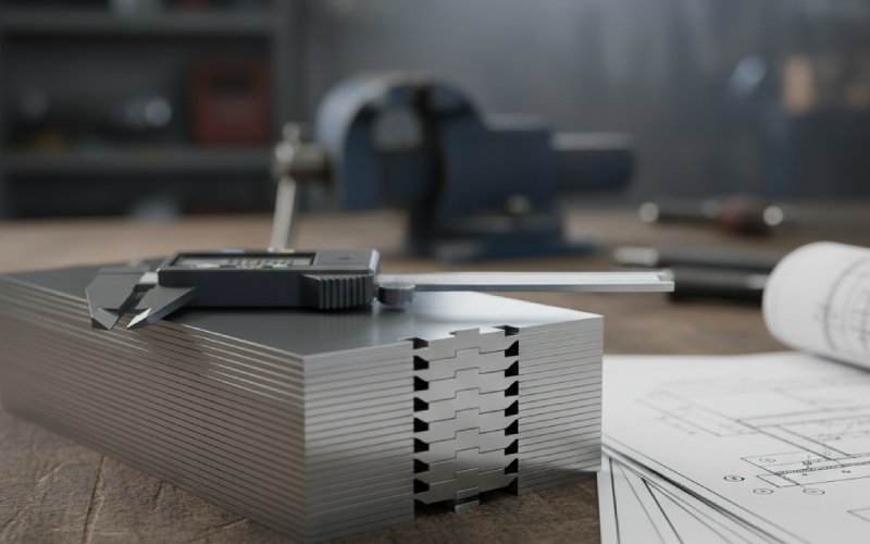
Lamination thickness usually 0.23–0.30 mm.
Amorphous metal cores (ribbon)
Lower hysteresis, very thin ribbon, lower resistive eddy-current loss.
No-load/core loss typically 0.2–0.4 W/kg @ 1.5 T, 50 Hz, so roughly 60–80% lower than CRGO for comparable designs.
Ribbon thickness around 0.025–0.03 mm, one order of magnitude thinner than standard CRGO.
The thing that trips people: amorphous wins strongly on core loss, but gives you:
Lower saturation flux density
Lower stacking factor
More fragile material and stricter core-processing window
That’s where design and purchasing start pulling in different directions.
2. Side-by-side: material-level comparison
These are typical values from published data sheets and technical notes, not guarantees for your specific grade or supplier.
Parameter (50 Hz ref.)
CRGO lamination (Hi-B type)
Amorphous metal core
Core loss @ 1.5 T, 50 Hz (W/kg)
~0.8 – 1.3
~0.2 – 0.4
Saturation flux density, Bs (T)
~1.9 – 2.03
~1.56 – 1.6
Typical thickness
0.23 – 0.30 mm
0.025 – 0.03 mm
Stacking/space factor
~0.96 – 0.97
~0.85 – 0.87
Form
Sheet / lamination stacks
Ribbon, wound or stacked cut ribbon
Processing temperature (annealing)
~800 °C
~360 °C
Typical use (today)
Power & distribution transformers, large units
Distribution transformers, energy-efficiency driven projects
So on paper, amorphous looks like a clear win for no-load losses. In practice, the lamination stack geometry, stress, and assembly quality pull those nice W/kg numbers towards reality.
3. Efficiency: beyond the W/kg line in the datasheet
3.1 No-load losses – where amorphous usually dominates
Across utilities and vendors, you’ll keep seeing the same range:
Amorphous distribution transformers: 60–80% lower no-load losses vs CRGO units of similar rating.
That reduction comes from:
much thinner lamination (≈ 0.025 mm ribbon)
higher resistivity
disordered atomic structure with lower magnetic anisotropy
So if your transformer sits energized 24/7 at low load—classic distribution case—the core loss slice of the pie is big, and amorphous tends to win the efficiency game almost automatically.
Where people get surprised: the relative gain shrinks when:
Flux density is derated strongly
Ambient temperature or cooling constraints force you to de-rate both designs anyway
Copper (load) losses dominate due to high average loading
In those projects, the “headline” 70% figure feels large but the system-level kWh saved per year may be modest.
3.2 Load losses, temperature, and lifetime
The usual story is “amorphous fixes core loss, copper loss stays about the same.” Not always.
Recent work on distribution transformers under high EV charging load found amorphous units showing ~18.6% lower load losses and significantly lower oil temperatures compared with CRGO units in comparable duty.
Why could that happen?
Different design approach once core loss budget is relaxed
Lower core heating, allowing more freedom on winding layout or conductor area
Possibly more conservative flux density, spreading losses in volume
You cannot assume this improvement; it depends heavily on the designer. But it’s a hint: once you change core material, the design space shifts. If the vendor re-optimizes, some copper loss may slide downward as a side effect.
For lifetime, lower hot-spot temperature is always welcome. Fewer thermal cycles at high temperature generally mean more margin on paper and pressboard ageing, oil quality, and gassing behavior.
But again, that’s design-specific, not something the material guarantees on its own.
3.3 Harmonics and distorted grids
Most documentation compares losses at pure sine wave excitation. Real grids, especially with EV chargers, PV inverters, and drives, are not so clean.
Studies on CRGO vs amorphous cores under harmonic load show that amorphous cores still keep a clear lead on loss, but the gap narrows as harmonics grow because eddy-current components behave differently in each material.
For engineers:
If you already model harmonic loss explicitly, don’t reuse CRGO factors blindly for amorphous.
Temperature rise tests under realistic load spectra become more important than a single “loss at 50 Hz” line.
4. Cost: where the money actually moves
The obvious part is:
Amorphous material cost per kg is usually higher than CRGO.
You need more kilograms of core because of lower Bs and lower stacking factor.
If you stop here, amorphous looks expensive. But lamination stacks are not just steel weight.
4.1 Material and lamination-stack costs
From a lamination/stack supplier view:
CRGO lamination stacks
Good nesting yield, especially with optimized step-lap cutting.
Stable slit coil supply chain, multiple mills, mature global capacity.
Thicker steel allows reasonably fast punching or laser cutting without extreme burr problems.
Amorphous core stacks / wound cores
Ribbon is much thinner and more fragile, cutting and handling need tighter process control.
Stacking factor around 0.86 means a bigger physical core area for same magnetic cross section.
More care around annealing and stress, or you lose a chunk of the theoretical loss advantage.
So on your RFQ:
The price per kg of stack will probably be higher for amorphous.
The kg required might also be higher.
But that’s not the end of the TCO story.
4.2 A very rough payback sketch
Take a simple thought experiment:
Amorphous core reduces no-load loss by, say, 60% against a CRGO design.
Assume the CRGO unit’s core loss is 500 W at rated voltage; amorphous comes out near 200 W for similar rating.
So ~300 W saved continuously.
Annual energy saved:
0.3 kW × 24 h × 365 ≈ 2,628 kWh/year.
Even at a modest electricity cost, that’s a non-trivial annual saving. Multiply by a 20+ year service life and discount it and you get a rough cap for how much extra CAPEX the amorphous core can justify.
You’ll plug in your real tariffs and duty, of course. The point: the economics are strongly grid-context dependent. Low utilization or short energization time? Savings collapse. High utilization, 24/7? Savings pile up.
4.3 System-level costs that often get missed
Tank and oil volume With lower Bs and stacking factor, amorphous cores may grow physically for the same rating. That can mean more tank steel and more oil, though, in some designs, careful geometry keeps the increase modest.
Logistics and footprint Slightly bigger footprint might matter on urban substations, rooftops, or pad-mount spaces. Check your civil constraints early.
Noise Lower magnetostriction in amorphous can help core noise at similar flux density, but designs often run at different Bmax, so you still need acoustic tests, not assumptions.
Repairability Field rewinding or core rebuilding is usually easier with conventional CRGO lamination stacks. Amorphous wound cores can be more painful to repair or modify on site.
5. Typical use cases – where CRGO lamination stacks still make sense
Despite all the energy-efficiency discussion, CRGO is not going away.
Typical situations where CRGO stacks remain a strong choice:
Large power transformers (sub-transmission, transmission)
High voltages, high flux density, well-understood mechanical behavior of stacked CRGO, and very optimized step-lap designs.
Project teams may prioritize proven long-term fleet data over incremental no-load loss reduction.
Projects with short duty cycles or low annual energized hours
If the transformer is de-energized often, or used mostly as backup, core loss savings shrink, so cheaper CRGO core is easier to justify.
Harsh mechanical environments
Heavy transport, frequent moves, seismic risk, unusual mounting — CRGO lamination stacks are mechanically forgiving compared with brittle amorphous ribbon stacks.
Retrofits where geometry is fixed
Existing tank, bus duct, or substation layout may simply fit CRGO footprint better.
Supply-chain risk avoidance
Multiple mills and service centers for CRGO steel. Amorphous capacity is still more concentrated, though growing.
6. Typical use cases – where amorphous cores earn their keep
On the other hand, amorphous cores often win on TCO in these scenarios:
Distribution transformers energized 24/7 at modest loading
Rural networks, long feeders, residential or light commercial loads.
No-load loss is a large share of total energy loss, so 60–80% reduction matters a lot.
Regulated high-efficiency classes
Where standards (for example, variants of IS 1180 and related efficiency schemes) push allowed no-load losses to very low values, amorphous helps reach those levels without oversizing everything else.
Green or ESG-driven projects
Utilities and large end-users explicitly valuing reduced grid losses and CO₂ footprint over simple CAPEX.
High harmonic urban networks with long duty
Even with harmonics, the no-load loss advantage stays significant, and lower temperature rise can provide useful headroom.
Compact, efficient medium-size transformers
Some vendors use higher permeability of amorphous material to design compact units (especially at lower flux). In practice, you need to look at the finished drawing, not just the marketing claim.
7. Lamination stack realities: what your supplier actually adjusts
When you shift from CRGO stacks to amorphous, your lamination/core supplier is not just swapping steel.
Key differences they juggle:
Cutting patterns and step-lap geometry
CRGO: very mature step-lap cutting to control local flux density and building factor.
Amorphous: ribbon-based wound cores or cut ribbond stacks require different patterns; mis-managed gaps and joints can degrade losses badly.
Residual stress and annealing
CRGO is sensitive to punching and clamping stress; annealing and strain management affect final loss and magnetostriction.
Amorphous cores depend heavily on correct field annealing; poor process can increase loss well above datasheet values.
Stacking factor vs window utilization
Lower stacking factor of amorphous means more apparent thickness for same active cross section.
That flows into winding window area, copper packing, and leakage reactance.
For purchasing teams, this means:
Ask not just for material grade, but process capability: annealing, core building factor, testing range, and traceability.
For amorphous projects especially, a “cheap but sloppy” core supplier can delete most of the theoretical advantage.
8. What to ask in RFQs – purchasing and engineering together
A short joint checklist that tends to surface real trade-offs:
Guaranteed loss values and test points
No-load and load losses at specified voltage and frequency.
Amorphous: alloy type, typical loss vs flux density curve, stacking factor, ribbon thickness.
Core processing guarantees
Building factor range, post-build annealing or stress relief steps.
For amorphous: maximum allowed handling or clamp stress, gap control, and repair policy.
Thermal and acoustic performance
Temperature rise limits at rated load and at planned overload profiles.
Guaranteed sound level at specified test positions.
Lifecycle and standards
Compliance with your local transformer efficiency standard (for example, IS-type, EU EcoDesign type, or equivalent).
Expected service life for core/winding insulation under typical duty.
Total cost side-by-side
Ask for TCO comparison (CAPEX + estimated lifetime loss cost) for both CRGO and amorphous designs at the same rating.
This forces real numbers into the discussion instead of general claims.
9. A quick decision sketch
Not a full tool, just a mental flow you can run in a meeting:
Is the transformer energized most of the year?
Yes → core loss matters a lot → favor amorphous, evaluate TCO carefully.
No → core loss contribution small → CRGO still very attractive.
Are you constrained by footprint or existing tank geometry?
Tight → check whether amorphous design fits without civil changes.
Do local standards push high efficiency classes?
Yes → check if CRGO designs can still meet allowed no-load losses without extreme oversizing; if not, amorphous is natural.
Is supply security and field repair a top concern?
Yes → CRGO may still be the safer option in some regions.
Are you able to evaluate supplier process quality, not just material?
If you can audit cores and test loss yourself, amorphous risk is easier to manage.
If you cannot, conservative CRGO might be simpler until that capability is built.
FAQ: CRGO lamination vs amorphous core
1. How much lower are amorphous core losses in real transformers, not just in theory?
Across many field reports and technical notes, 60–80% lower no-load losses compared with CRGO transformers of similar rating is a realistic range, provided the amorphous core is processed correctly. Design choices and flux density will move the exact number, but if you see only a 10% improvement, something is probably off.
2. Does an amorphous transformer always have lower total losses (core + copper)?
Not always. Amorphous almost always cuts core loss, but total loss also depends on: How the designer trades off copper area vs temperature rise Target flux density in each design Harmonic content of the load current Some recent studies have shown amorphous units even achieving lower load losses and cooler oil because designers used the freed-up loss budget to improve winding design. But you should treat that as a design outcome, not a material guarantee.
3. Are amorphous core transformers always smaller and lighter?
No. That’s one of the more confusing claims. Amorphous metals can support efficient designs and sometimes allow compact units, but: Lower saturation flux density and lower stacking factor often mean more core volume for the same rating. That can increase tank size and oil volume, even if some vendors manage clever work-arounds. Some marketing material shows smaller prototypes at specific ratings or flux, which doesn’t always generalize. Check the actual outline drawing and weight schedule for both options at the same rating before assuming a size advantage.
4. Do regulations force me to move from CRGO to amorphous?
In most markets, regulations don’t name the material, they limit allowable losses for certain transformer classes (kVA, voltage, cooling). You can still meet these with high-grade CRGO in many cases, but as allowed no-load losses shrink, designs become larger and more expensive if you stay with CRGO. At some point, amorphous becomes the easier route to compliance.
5. Is CRGO being phased out globally?
No. CRGO is still widely used in power and distribution transformers and actively developed (thinner Hi-B grades, better coatings, improved grain orientation). What is changing is the mix: more amorphous units for high-efficiency distribution, while many large power transformers and cost-sensitive projects stay on CRGO for now.
6. What should I ask a lamination or core supplier who offers both?
A few focused questions usually reveal a lot: For CRGO lamination stacks: “What building factor range do you typically achieve at my flux level?” “How do you control punching stress and burrs for my thickness range?” For amorphous cores: “What annealing profile do you use, and how do you monitor it?” “What’s your typical no-load loss deviation between sample test cores and full production?” “How do you handle rework if a core fails loss tests?” If the answers are vague, the quoted W/kg number on the datasheet is less comforting.
7. What’s the simplest way to choose between CRGO and amorphous for a new project?
Very short version: If the transformer is energized almost all the time, and energy cost is meaningful → run a lifetime loss cost calculation with amorphous and see if the payback period is acceptable. If it is backup, rarely used, or extremely CAPEX-sensitive → CRGO lamination stacks will often remain the practical choice. If in doubt → request parallel quotes from the same vendor for both core options at the same rating, same cooling, and same loss guarantees, then compare: kW loss, kg of copper and steel, footprint, and price. That comparison usually makes the trade-off very visible in one spreadsheet tab.
Cheney is a dedicated Senior Application Engineer at Sino, with a strong passion for precision manufacturing. He holds a background in Mechanical Engineering and possesses extensive hands-on manufacturing experience. At Sino, Cheney focuses on optimizing lamination stack manufacturing processes and applying innovative techniques to achieve high-quality lamination stack products.
New Product Brochure
Please enter your email address below and we will send you the latest brochure!
Let Sino's Lamination Stacks Empower Your Project!
To speed up your project, you can label Lamination Stacks with details such as tolerance, material, surface finish, whether or not oxidized insulation is required, quantity, and more.