Let Sino's Lamination Stacks Empower Your Project!
To speed up your project, you can label Lamination Stacks with details such as tolerance, material, surface finish, whether or not oxidized insulation is required, quantity, and more.
Domain-Refined CRGO Lamination: Laser Scribing, Coatings, and Real-World Loss Reduction
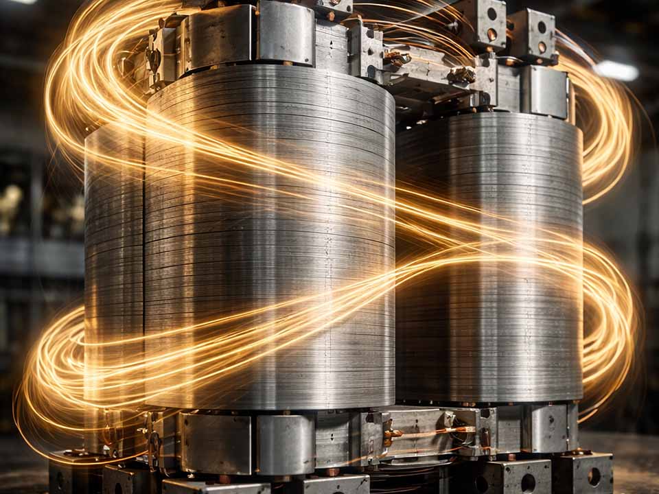
When you walk past a big power transformer, everything looks still. Inside, though, billions of tiny magnetic domains are shuffling back and forth 50 or 60 times per second. Every unnecessary shuffle becomes heat, noise, and lost kilowatt-hours.
Domain-refined CRGO is about teaching those domains to move smarter, not harder. In this article we’ll go deep into how laser scribing, coatings, and lamination practice actually work together to cut losses in the real world – not just in catalogues.
Who is this for?
Transformer design engineers trying to justify premium CRGO or DR grades
Purchasers and specifiers who need more than “P1.7/50 = x W/kg” on a datasheet
Anyone who wants a practical, physics-aware mental model of domain refinement
Table of Contents
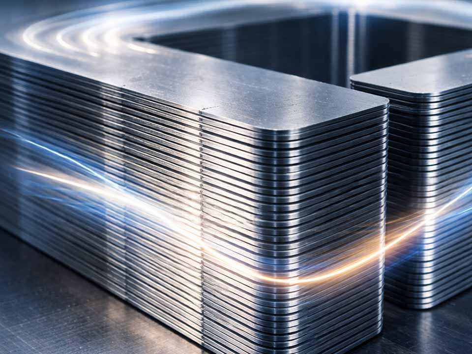
1. CRGO laminations in one mental picture
Cold-rolled grain-oriented (CRGO) steel is like a crowd where almost everyone is already facing the same way. Through controlled alloying and rolling, manufacturers develop a sharp Goss texture so the {110}〈001〉 direction lines up with the rolling direction, giving very high permeability and low hysteresis along that axis.
Core loss in those laminations is still made up of three main parts: hysteresis, classical eddy currents, and so-called “excess” or abnormal eddy current losses – the messy bit tied to domain wall motion and local microstructure.
Core loss components (and what we can actually influence):
Hysteresis loss – energy lost every time domains switch direction; linked to alloy and texture.
Classical eddy current loss – set mainly by sheet thickness, resistivity, and frequency (∝ t² f² B²), so thin gauges help.
Excess / anomalous loss – extra currents and friction around moving domain walls; highly sensitive to domain size, stress, and defects.
Magnetostriction & stress sensitivity – not a loss term by itself, but strongly coupled to noise, coating tension, and processing stresses.
2. What domain refinement really does
In untreated CRGO, you typically get broad 180° domains running more or less along the rolling direction. When the AC flux reverses, domain walls have to travel relatively long distances; that’s where a lot of the abnormal eddy and hysteresis loss lives.
Domain refinement techniques deliberately “chop” these wide domains into finer stripes by introducing controlled surface stresses. These stresses create closure and 90° domains that subdivide the main 180° domains. The distance that walls move during each cycle shrinks, and so do the associated excess losses and magnetostriction effects.
Measured impact from research and industry:
Industrial CO₂ and Nd:YAG laser scribing: ≈10% typical core-loss reduction at constant grade, thickness, and test conditions.
Fiber-laser LMDR: lab work reports ≈13% loss reduction with “invisible” scribe lines optimized for stress rather than visible grooves.
Two-sided laser scribing in a magnetic field: up to 16.8% reduction compared to 9.7% for conventional single-side scribing.
Industrial laser scribing machines quote up to ~14% loss reduction on GOES cores.
Picosecond-laser domain refinement has demonstrated ≈15–16% lower iron loss and noticeable reductions in coercivity and residual magnetism.
These numbers are why domain-refined (DR) grades and LMDR processing have become mainstream for high-performance cores rather than a niche R&D trick.
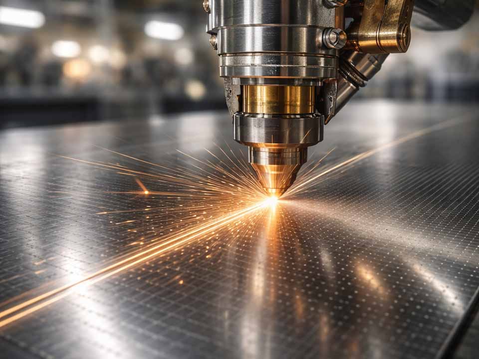
3. Laser scribing: from theory to the lamination line
At plant level, laser scribing isn’t a mysterious “magic” pass. It’s a tightly controlled thermo-mechanical treatment step inserted after the steel mill’s final coating and before the laminations are cut and stacked.
A focused laser beam scans across the sheet, creating lines perpendicular or at a slight angle to the rolling direction. The local heating and rapid cooling introduce a narrow region of residual stress. That stress field is what forces domains to subdivide – not the groove itself.
Key process knobs for LMDR / laser scribing:
Beam type & wavelength – CO₂ and fiber lasers dominate industry; shorter-wavelength picosecond lasers can refine domains with less coating damage.
Energy per unit length – too low: domains barely change; too high: coating damage, surface melting, and even degraded loss. There’s a narrow “sweet band” of energy density.
Line spacing – closer spacing generally improves loss until a saturation point, beyond which damage and stress interaction can reverse the benefit.
One-side vs two-side – two-side scribing, especially in a magnetic field, can deliver larger improvements (≈16–17%) but adds cost and complexity.
Pattern design – straight, periodic lines are common, but “invisible” shallow patterns and hybrid groove/thermal-shock patterns are increasingly used to optimize stress without over-etching.
4. Coatings: the quiet partner in domain refinement
If laser scribing is the loud innovation, coatings are the quiet enabler. Modern GOES leaves the mill with:
A Forsterite (Mg₂SiO₄) base glass film grown during high-temperature annealing. This chemically bonds to the steel, provides a foundation for tension, and protects the surface.
An inorganic phosphate-rich insulation / tension coating on top, often silica + metal phosphate with specific additives (e.g., nitrides) to tune tension, adhesion, and resistivity.
These coatings don’t just electrically insulate laminations; they actively hold the sheet under in-plane tensile stress. That tension reduces magnetostriction and can lower loss by stabilising domain structures – especially once laser-induced micro-strains are added to the mix.
Why coating chemistry really matters for DR CRGO:
Interlaminar resistance: too low → circulating currents between laminations eat away your LMDR gains; too high → can compromise stacking factor or crack under stress.
Tension consistency: phosphate composition and crystallization behavior (Mg vs Al-phosphate systems, for example) change the stress state and therefore domain patterns.
Coating robustness: aggressive scribing parameters can roughen or break the coating, increasing local loss and long-term corrosion risk. Optimised LMDR recipes aim to refine domains without compromising the coating.
Annealing stability: some early DR steels showed loss “bounce-back” after stress-relief annealing; modern heat-proof DR grades and advanced coatings are engineered to retain refinement even after high-temperature treatment.
5. How much loss reduction can you realistically expect?
Manufacturers and papers quote different numbers, partly because they test at different flux densities, frequencies, and sample geometries. Still, there are clear trends:
Standard high-permeability CRGO at ~0.27 mm might sit around ~1.0–1.1 W/kg at 1.7 T, 50 Hz, depending on grade and supplier.
Domain-refined high-induction grades of similar thickness often guarantee around 0.90 W/kg or below at the same test point.
LMDR or enhanced scribing tends to shave another few tenths of a watt per kilogram, particularly at higher induction levels or frequencies.
Instead of chasing a single “magic” number, it’s more useful to compare options by relative improvement and context:
Example comparison of lamination and treatment options
(Illustrative ranges – always check your specific supplier datasheets.)
Option
Typical thickness (mm)
Example P1.7/50 range (W/kg)
Loss change vs base CRGO
Coating / treatment notes
Conventional HI-B / high-perm CRGO
0.27–0.30
~1.00–1.10
Baseline
Forsterite + standard phosphate coating
Domain-refined CRGO grade (mill DR)
0.23–0.27
~0.85–0.95
≈5–15% lower
Factory-applied domain refinement + tension
LMDR / laser-scribed on top of DR grade
0.23–0.27
~0.75–0.90
≈10–17% lower overall
Optimised laser scribing, coating-safe recipe
Ultra-thin DR CRGO (≤0.20 mm), laser-scribed
0.18–0.23
often <0.80
Thickness + DR + LMDR
Very sensitive to burrs & handling
This is why serious high-efficiency transformers increasingly specify not just “CRGO”, but “DR CRGO + LMDR + thin gauge” as an integrated package.
Design takeaways from the numbers:
Don’t compare grades only on absolute W/kg; normalize by thickness, induction, and whether DR / LMDR is included in the spec.
For a fixed core window and flux density, moving from conventional HI-B to DR + LMDR grades can free up several hundred watts in large power transformers – often worth the extra steel cost over 30–40 years of service.
Thinner gauges plus domain refinement shine most in high-induction designs and higher frequencies (e.g., 60 Hz grids or special applications), where eddy and excess losses are dominant.
6. Integrating laser scribing into your core manufacturing flow
From an operations perspective, adding LMDR isn’t just about buying a laser. It’s a system-level change that must cooperate with slitting, cutting, annealing, stacking, and quality control.
Typically, scribing is applied either on the full-width coil or on slit coils before final cutting. The LMDR line needs precise tension control, tracking, and feedback to keep line spacing and energy density within a tight window across kilometers of strip.
Practical integration checklist:
Decide where to scribe: full width (simpler path control) vs. slit width (better alignment with final lamination geometry).
Align with coating robustness: confirm with the steel mill which coating class (e.g., ASTM A976 C-3/C-5 equivalents) is on the strip and its stress-relief limits.
Synchronize with stress-relief annealing: some DR patterns relax at higher annealing temperatures – or shift – if the cycle isn’t tuned. Request data on loss before/after your exact annealing conditions.
Measurement loop: use single-sheet testing (SST) on treated and untreated samples to directly quantify the LMDR boost at your design induction. ([Corefficient][18])
Noise and vibration correlation: track changes in magnetostriction-driven noise; LMDR often reduces audible hum, but not if mechanical clamping or joint design are poor.
7. Coating and LMDR interactions engineers often overlook
In many blogs, coatings get one paragraph; in real transformers, they can make or break your domain-refined design. Experiments on phosphate-based coatings show that small changes in phosphate ratio and crystallization can significantly affect loss and magnetostriction by modifying the in-plane tensile stress. On top of that, newer coating formulations add nitrides or ceramic fillers to extend stress-relief annealing capability and increase interlaminar resistance – exactly the properties you want if you’re layering laser-induced stress on top.
Questions to ask your steel supplier about coatings (specifically for DR/LMDR applications):
What is the coating type and class (e.g., internal designation + ASTM A976 family)?
What is the tension window (MPa range) and how stable is it after stress-relief annealing at your planned temperature?
Is the coating explicitly qualified for laser scribing, and at what maximum line energy / power density?
How does interlaminar resistance vary before and after a representative LMDR pass?
Are there recommended cleaning limits (no pickling, no abrasive blasting, etc.) that could disturb coating performance?
8. Pitfalls that can erase your domain-refinement advantage
Not all “domain-refined” transformers are equal. If you’re unlucky, process mistakes downstream of the steel mill can quietly give back most of the gains you paid for.
Cutting methods, burr height, and mechanical clamping all introduce stresses that reshuffle domains and can localize flux. Even with high-grade DR steel, a poor cutting process (excessive burrs, work-hardening) can raise localized loss and noise near edges. Stress-relief annealing and rewinding can also partially undo LMDR, especially if temperatures or atmospheres deviate from those used to qualify the grade.
Common failure modes (and human-level ways to spot them):
Coating scorching or cracking along scribe lines – visible discoloration, rough grooves, or flaking; often correlates with worse-than-expected no-load loss after assembly.
Loss “snap-back” after annealing – SST or Epstein tests show good improvement immediately after LMDR, but much smaller gains after your full core process.
Edge hot spots – thermography or flux-density mapping reveals localized heating at joints or cut edges, indicating that cutting stress has overwhelmed domain refinement benefits.
Unstable performance between batches – signs that the laser or line isn’t holding energy/spacing tolerances, or that coil/grade mix is inconsistent.
Noise complaints despite low catalogue loss – often a joint / clamping / magnetostriction problem rather than fundamental steel quality.
9. Turning all this into a specification that beats your competitors
Your competitors may already be saying “we use laser-scribed CRGO” on their websites. To genuinely outperform them, you need a spec that ties together material selection, LMDR, coatings, and process control – and you need to enforce it with data.
Rather than writing a vague “CRGO, domain refined, low loss” line in the spec, build a small but sharp requirement set that links physics to numbers and QA.
Elements of a robust, future-proof CRGO lamination spec:
Grade and thickness: specify the exact domain-refined grade family (e.g., DR high-induction series, 0.23 or 0.27 mm) with maximum P1.7/50 and P1.5/60 values.
Domain refinement method: require LMDR or equivalent laser scribing, with minimum relative loss reduction vs. untreated reference at your chosen induction (e.g., ≥10% at 1.7 T, 50 Hz).
Coating performance: call out coating class, minimum interlaminar resistance, and confirmation of coating integrity after LMDR and stress-relief annealing.
Process-linked limits: maximum burr height, joint design (step-lap geometry), and acceptable stress-relief annealing windows.
Verification: require SST or Epstein test data showing before/after LMDR performance, plus periodic audits during mass production.
10. Closing thoughts
Domain-refined CRGO isn’t just a better catalogue line; it’s a way of reshaping the invisible magnetic landscape inside your transformer core. Laser scribing, coatings, and lamination practice are all levers acting on the same physical system: domain structures, stress fields, and eddy currents.
When those levers are aligned, you genuinely can see double-digit reductions in core loss and a meaningful drop in noise – not just in isolated test strips, but in fully built transformers running on the grid for decades. When they’re misaligned, “domain refined” becomes just another buzzword that hides avoidable watts and disappointed customers.
If you design, build, or specify transformer cores, thinking in terms of domains + stress + coatings + process will put you a step ahead of competitors who only look at a single loss number on a datasheet. That’s where the real edge in domain-refined CRGO lamination lives.
Share your love
Sino
Sino Lamination is your expert partner for custom lamination stacks, engineering cores for the most demanding applications. Our expertise covers a comprehensive range of assembly techniques, from state-of-the-art adhesive bonding for superior performance to proven methods like welding and riveting. We serve diverse industries including automotive, robotics, and energy, delivering precision-stamped cores for any project. We are dedicated to providing the high-quality, reliable lamination stacks that empower our clients’ innovations and drive their success.
New Product Brochure
Please enter your email address below and we will send you the latest brochure!
Let Sino's Lamination Stacks Empower Your Project!
To speed up your project, you can label Lamination Stacks with details such as tolerance, material, surface finish, whether or not oxidized insulation is required, quantity, and more.