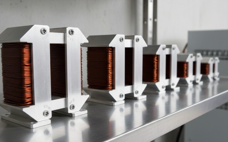
Let Sino's Lamination Stacks Empower Your Project!
To speed up your project, you can label Lamination Stacks with details such as tolerance, material, surface finish, whether or not oxidized insulation is required, quantity, and more.
If you’ve ever been caught between EI laminations that are easy to build, toroids that are wonderfully efficient but tricky to wind, and R-cores that aim for the best of both, the double C-core transformer sits in a sweet, under-explained middle ground. This guide blends what the best articles cover with the hands-on detail and trade-offs engineers actually use when they commit to double C-cores in production. We’ll define the geometry, compare it with alternatives, dig into materials (GO steel, amorphous, nanocrystalline), highlight failure modes and tolerances, and finish with an ROI mini–worksheet you can adapt to your project.
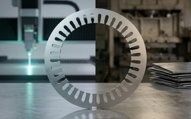
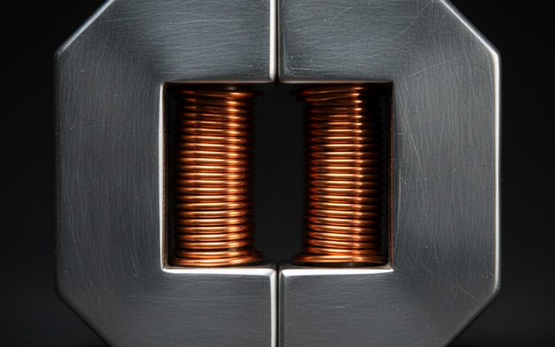
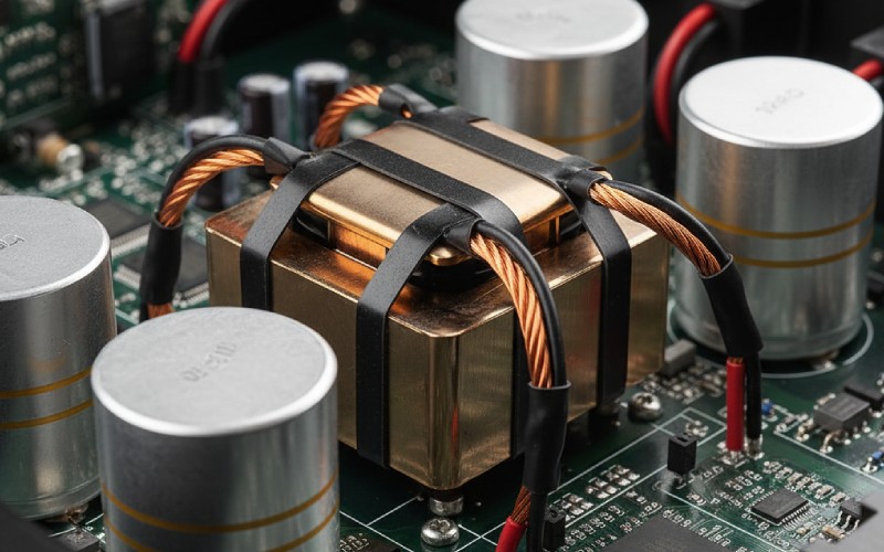
A cut-core (C-core) starts as a wound steel strip on a rectangular form that’s heat-treated and then sliced into two “C” halves; mating the polished faces completes the magnetic path. A “double C-core” uses two such sets, a shell-style build that envelops the windings and reduces leakage compared with a single C. The C-core method keeps flux aligned with the steel’s grain, lowering reluctance versus many stacked laminations.
Compared to EI stacks, C-cores exploit grain orientation more fully and typically radiate less stray flux; compared to toroids, they’re easier to wind and fixture while still offering a compact magnetic path. In audio and other noise-sensitive contexts, C-core construction is often chosen specifically to reduce leakage and hum without toroidal winding complexity.
| Geometry | Magnetic path breaks | Typical leakage/EMI | Winding/assembly effort | Material utilization | Notes / Best for |
|---|---|---|---|---|---|
| EI (stacked) | Multiple joints | Higher without bands/cans | Easy, standardized | Partial grain use | Lowest part cost; needs shielding in sensitive gear. |
| Double C-core | Two joints per set (four halves) | Low–moderate | Moderate; easy bobbin winding | Excellent grain use | Good balance of leakage vs build effort; strong in audio/industrial. |
| Toroid | None (continuous) | Very low | High (winding/lead exit) | Excellent | Top efficiency/EMI, harder to manufacture at scale variants. |
| R-core | None (continuous strip) | Very low | Moderate (special bobbins) | Excellent | Very low leakage and noise in medical/audio supplies. |
You can build double C-cores from GO silicon steel, amorphous alloys, or nanocrystalline ribbon. Materials aren’t just about losses—they drive noise, size, and robustness.
C-cores are cut, so joint quality drives performance. Polished, closely matched faces minimize the effective air gap. Designers often angle-cut the joint or lap the faces to further reduce reluctance. Stacking factor still matters—insulation in laminated stacks reduces effective area; cut-cores mitigate some of that by being wound strips, but windows and insulation still set limits on copper fill.
A good double C-core’s geometry and symmetry help cancel stray fields. Vendors targeting pro audio advertise low mechanical noise, and field experience backs up the choice of C-cores for low hum without resorting to potting cans. If you go amorphous for ultra-low core losses at mains frequency, budget attention for magnetostriction—amorphous can buzz more unless you dial down flux density and use damping.
If BOM pressure is tight, a “C–I” approach (one cut C plus a laminated “I” bar) mimics the magnetic circuit of a double C-core with lower tooling and easier copper winding directly on the I bar. It’s a genuine production lever when you want many of the C-core benefits without the full cost of two matched cut cores.
Many comparisons stop at “toroid = most efficient,” but the nuance is operating profile and winding practicality. Toroids do minimize leakage and can trim copper and core loss, yet a double C-core with amorphous or nanocrystalline steel can rival those savings at mains or MF, while making multi-chamber, high-clearance windings far less painful. For voltage-sensitive loads and sensitive front-ends, the leakage/noise balance often favors double C with thoughtful construction.
Say your legacy 1 kVA EI unit idles most of the time. Swapping to a double C-core with an amorphous ribbon reduces core loss by, conservatively, 60–70%. If the old unit’s no-load loss is 40 W, the amorphous double C could bring it to ~12–16 W, saving ~210–245 kWh/year at 24/7 duty. At $0.15/kWh, that’s ~$31–$37/year, per transformer—before reduced HVAC overhead. Scale that across a rack or plant and the payback window narrows fast. Actual savings depend on flux density, sheet thickness, anneal, and assembly quality.
Even experienced teams lose performance to tiny mechanical errors around the C-core joint, sloppy clamping, or unbalanced leg windings. Treat the magnetic joint like a precision bearing surface.
A tight RFQ saves you from “good enough” cut cores. Here’s a concise set:
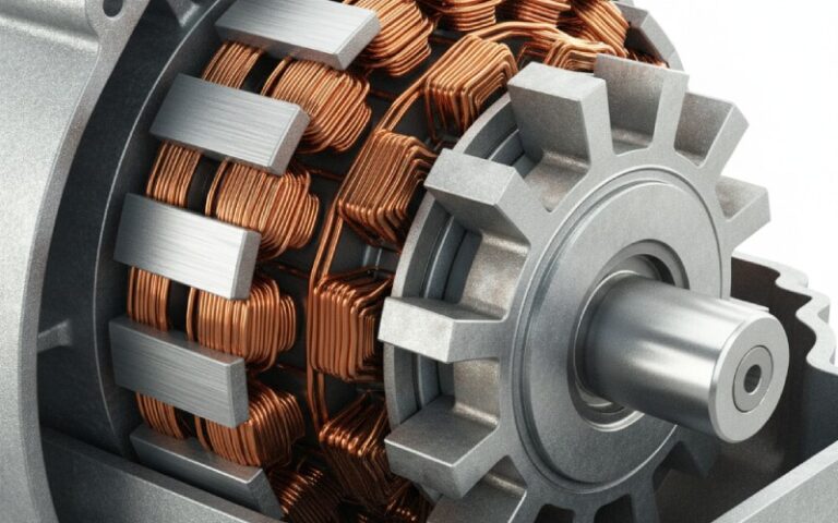
Engineers gravitate to double C-cores because they give you space and symmetry: room for sectionalized windings, shields, fuses, and thermal sensors on straightforward bobbins; symmetry that calms leakage and acoustic noise; and material options that let you bias toward efficiency (amorphous), frequency/size (nanocrystalline), or ruggedness (CRGO) without upending your manufacturing flow. When paired with a tight assembly spec and a vendor who understands joint finish and banding, you can land a transformer that’s quiet, efficient, and easy to build at scale—without the compromises of EI leakage or toroidal winding pain.