Let Sino's Lamination Stacks Empower Your Project!
To speed up your project, you can label Lamination Stacks with details such as tolerance, material, surface finish, whether or not oxidized insulation is required, quantity, and more.
Every gram on a drone is borrowed from flight time. That simple fact makes lamination stack design for drone motors one of the more unforgiving engineering problems we deal with on the production floor. You can’t just scale down an automotive motor core and call it a day. The constraints are different. The physics doesn’t care about your schedule.
This post covers what we’ve learned running custom lamination stacks for BLDC drone motors across micro FPV platforms, agricultural sprayers, and mid-size industrial UAVs. We’ll go through material tradeoffs, gauge selection, slot-pole geometry, stacking methods, and a few places where conventional wisdom gets it wrong.
A typical industrial motor runs at fixed load, maybe 1500 RPM, for years. A drone motor hits 25,000 RPM, drops to hover, punches full throttle again — all within seconds. The electrical frequency is high. The duty cycle is brutal. And the stator might weigh 12 grams.
That means:
So the lamination stack has to do more with less.
Bottom line: Drone motor laminations operate at 5–20× the electrical frequency of typical industrial motors, in a package with essentially zero thermal headroom. Standard industrial lamination practice doesn’t transfer.
Picking the right electrical steel for a drone motor isn’t a spec-sheet exercise. It’s a three-way negotiation between gauge thickness, core loss per kilogram, and processability at small diameters.
Most drone motor stators we produce use non-oriented silicon steel in 0.2 mm or 0.1 mm gauges. At the electrical frequencies drone motors run — typically 400 Hz to 1,500 Hz depending on pole count and RPM — thinner laminations cut eddy current losses substantially.
The math is straightforward. Eddy current loss is proportional to t^2 f^2 B^2, where t is lamination thickness, f is frequency, and B is flux density. Go from 0.35 mm to 0.2 mm and eddy current loss drops by roughly 67%. Go to 0.1 mm and you’re looking at around 92% reduction compared to 0.35 mm — on the eddy current component alone.
But thinner isn’t free. At 0.1 mm, the steel becomes harder to stamp cleanly. Burr control gets tighter. Die wear accelerates. And the stacking factor drops — you’re stacking more sheets with more insulation layers per unit height, so the effective magnetic cross-section shrinks. On our 0.1 mm stamping lines, we hold burr height under 15 µm across full production runs, which requires dedicated die clearance profiles and in-line optical inspection at every 500th stroke. That level of process control is the cost of playing at this gauge.
Cobalt-iron alloys hit saturation flux densities around 2.35 T, compared to roughly 1.8–2.0 T for silicon steel. That means you can push more flux through a smaller cross-section — translating directly to a lighter, more compact stator for the same torque output.
We’ve run cobalt-iron laminations for specialty drone programs — typically aerospace-adjacent UAVs with payload budgets measured in single-digit grams. The material cost is 8–12× that of silicon steel. It’s brittle. It requires different die clearances, slower stamping speeds, and controlled-atmosphere annealing.
For most commercial drone motors? Not worth it. The weight savings on a 20 mm OD stator might be 2–3 grams. The cost increase makes the entire motor non-competitive. Save cobalt-iron for programs where the weight budget is existentially tight.
Amorphous strips at 0.025 mm have absurdly low core loss — 70–90% lower than silicon steel. They also have a saturation flux density of only about 1.56 T, they’re brittle after annealing, and they can’t be stamped with conventional progressive dies.
We produce amorphous cores for drone motors via wire-EDM cutting, but only for prototype and low-volume OEM programs. The processing time and cost make mass production impractical today. Watch this space in 3–5 years, but don’t design your next product line around it.
Bottom line for designers: 0.20 mm non-oriented silicon steel is the right starting point for 90% of commercial drone motor programs. Move to 0.10 mm for competition or premium platforms where efficiency justifies the cost. Cobalt-iron and amorphous alloys are edge cases — real, but narrow.
This table reflects what we actually run on the production floor — not theoretical ideals. It’s based on hundreds of OEM stator core programs across the last several years.
| Motor Configuration | Typical Electrical Frequency | Recommended Lamination Gauge | Core Loss Reduction vs. 0.35 mm | Production Notes |
|---|---|---|---|---|
| 12N14P, micro FPV (< 25 mm OD) | 800–1,500 Hz | 0.10 mm | ~85–92% (eddy current component) | Requires precision progressive die; stacking factor ~0.93; burr height controlled < 15 µm |
| 12N14P, mid-size (25–40 mm OD) | 600–1,200 Hz | 0.15–0.20 mm | ~65–80% | Sweet spot for volume production; good die life; compatible with bonding and interlocking |
| 9N12P, agriculture/industrial | 400–800 Hz | 0.20–0.25 mm | ~50–65% | Higher torque application; wider teeth tolerate thicker lam |
| 24N22P, heavy-lift (> 50 mm OD) | 300–600 Hz | 0.20–0.35 mm | ~30–55% | Lower frequency allows thicker gauge; cost-driven decision |
The 0.20 mm grade sits at the center of most drone programs we handle. It’s thick enough to stamp reliably at high speed, thin enough to keep losses manageable up to about 1,000 Hz, and widely available from multiple steel mills. We maintain material traceability on all incoming coils — each lot is tested for thickness tolerance (±0.005 mm), Epstein loss at 400 Hz/1.0 T, and surface insulation resistance before it enters the stamping line.
Drone motors are almost universally outer-rotor BLDC with fractional-slot concentrated windings. The rotor spins around the stator, magnets on the inside of the bell, stator teeth facing outward. This topology favors high torque density at low speed — exactly what a propeller wants.
The two dominant configurations in the drone world:
From a lamination perspective, the slot-pole choice constrains tooth width. Narrower teeth (more slots) saturate more easily, especially at the tooth tips where flux concentration is highest. If you’re running 0.1 mm laminations with a stacking factor of 0.93, the effective tooth cross-section shrinks further. We’ve seen cases where a motor designed on paper at 1.5 T tooth flux density actually runs at 1.8 T or above once stacking factor and real geometry are accounted for — pushing into saturation and wiping out efficiency gains from the thin lamination.
The fix isn’t always thinner steel. Sometimes it’s adjusting the slot opening, widening the tooth tip, or going to a higher pole count (like 14P18S) to redistribute flux. This is a conversation that should happen between the motor designer and the lamination manufacturer before the die is cut. Not after. We run DFM reviews on every new stator geometry specifically to catch these issues — checking tooth flux density at the actual stacking factor, verifying slot fill targets, and flagging any features that won’t stamp cleanly at the target gauge.
Bottom line: Slot-pole geometry and lamination gauge are coupled decisions. Optimizing one in isolation from the other is how drone motor projects end up with prototype stators that test well but can’t be manufactured at volume.
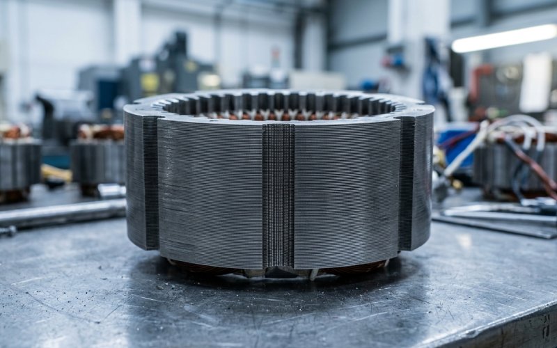
The three stacking methods relevant to drone motor laminations are interlocking, bonding (including self-bonding/backlack), and laser welding. Each has real tradeoffs at drone scale.
Rectangular or circular interlock tabs are stamped into each lamination during progressive die operation. The tabs mechanically lock sheets together as they stack.
Adhesive is applied to lamination surfaces either as a pre-coated backlack (self-bonding varnish activated by heat and pressure) or via glue dot dispensing during stacking.
For drone motors where efficiency is the primary metric, bonding is the better choice. We see roughly 5–8% improvement in total core loss compared to interlocked stacks of the same geometry and material. That translates directly to lower operating temperature and, in practice, measurably longer hover time.
Our bonding line runs both glue-dot dispensing and backlack activation. Adhesive thickness is held under 4 µm, and we validate peel strength on sample cores from every production batch — minimum 2 N/mm² after cure.
Thin weld lines along the outer diameter of the stator stack.
We still produce welded drone stator stacks — usually for customers optimizing cost on high-volume consumer platforms. But if a client asks how to squeeze another 2–3% efficiency out of their motor, switching from welding to bonding is usually the first suggestion.
Bottom line: Bonding delivers the best electromagnetic performance for drone motor stators. Interlocking wins on speed and cost for mass production. Welding is a compromise — fast and strong, but with a real core loss penalty that matters at drone scale.
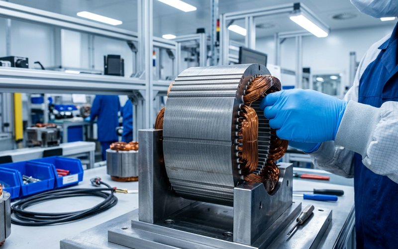
Most drone stator stacks receive an electrostatic epoxy powder coating after stacking — typically 0.20–0.30 mm thick. The coating insulates the stator from the winding, protects against corrosion, and provides some mechanical damping.
The weight penalty is real. On a small stator (say 18 mm OD, 5 mm stack height), a 0.25 mm coating adds roughly 0.5–0.8 grams. That doesn’t sound like much until you’re building a 250-class racing quad where the motor weighs 28 grams total. Now it’s 2–3% of motor mass contributing zero electromagnetic function.
Our approach: we control coating thickness down to 0.15 mm for weight-critical applications, with a variance of no more than ±0.02 mm across the stator surface. Achieving this requires precise electrostatic charge control, part temperature management during application, and a validated cure profile (typically 180°C for 20–30 minutes depending on the epoxy system). For competition-grade motors, some clients skip the coating entirely and rely on winding insulation alone. That’s a durability tradeoff we leave to the motor designer.
Bottom line: Standard 0.25 mm epoxy coating adds ~0.5–0.8 g on a small drone stator. We can halve that to 0.15 mm with tighter process control. Skipping it entirely saves more weight but requires the winding insulation to carry the full dielectric burden.
We’ve done enough back-and-forth with motor designers to have a feel for where lamination choices create real-world endurance gains. Here’s the rough hierarchy, ordered by impact:
0.20 mm is the most common production gauge and the right starting point for most programs. It balances core loss reduction, die life, and cost across the widest range of drone motor sizes (15–50 mm OD stators). For micro FPV motors under 20 mm OD running above 1,000 Hz electrical, 0.10 mm is measurably better but costs more to produce. We offer both gauges in progressive die stamping.
Bonding (glue dot or backlack) gives better electromagnetic performance — lower core loss, no inter-laminar shorts, quieter operation. Interlocking is faster and cheaper for mass production. If efficiency and thermal performance are priorities, bonding is worth the additional process step. If you’re making 500K motors a year for a consumer quad and cost is king, interlocking with a well-controlled die works fine. We run both processes and can provide comparative test data on your specific geometry.
Not yet at volume. Amorphous strips offer dramatically lower core loss but can’t be stamped with progressive dies. Wire-EDM cutting works for prototypes and short runs. The material is also brittle after annealing, which complicates handling in a small motor assembly. We produce amorphous drone cores for R&D and limited OEM programs, but it’s not a mass-production solution today.
Higher pole counts increase electrical frequency at a given RPM, which increases core loss. This creates a push toward thinner laminations. But higher pole counts also mean narrower stator teeth, which reduces flux-carrying area and makes saturation more likely. The lamination design and the motor electromagnetic design need to be co-optimized — not done sequentially. We run DFM checks on tooth flux density during every new die quotation.
Roughly 0.5–1.0 grams on a typical micro/mini drone stator (18–25 mm OD), depending on coating thickness. We control thickness down to 0.15 mm with ±0.02 mm variance for weight-sensitive applications. Dropping from 0.30 mm to 0.15 mm coating saves about 0.3–0.5 grams per stator — small, but meaningful at the motor level.
Only in edge cases — military UAVs, high-altitude platforms, or applications where payload capacity is valued at hundreds of dollars per gram. For commercial and consumer drones, the 2–3 gram weight savings on a typical small stator doesn’t justify the 8–12× material cost premium. High-grade 0.10 mm silicon steel gets you 90% of the benefit at a fraction of the price.
Higher pole counts increase electrical frequency at a given RPM, which increases core loss. This creates a push toward thinner laminations. But higher pole counts also mean narrower stator teeth, which reduces flux-carrying area and makes saturation more likely. The lamination design and the motor electromagnetic design need to be co-optimized — not done sequentially. We run DFM checks on tooth flux density during every new die quotation.
For a new progressive die: 3–4 weeks for die fabrication, plus 1 week for first article samples. If your stator dimensions match one of our existing open tooling specifications (we maintain over 80 die sets for common drone stator OD/ID/slot combinations), sample lead time drops to about 5–7 business days. Production runs typically ship within 2 weeks after sample approval.
→ Request a free DFM review of your drone stator design. Send us your stator drawing or specifications — we’ll come back within 48 hours with a manufacturing feasibility assessment, recommended gauge and stacking method, and a budgetary quote covering prototype through volume production.