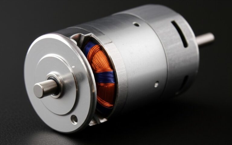
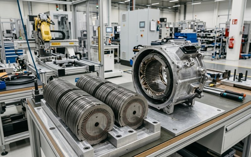
Let Sino's Lamination Stacks Empower Your Project!
To speed up your project, you can label Lamination Stacks with details such as tolerance, material, surface finish, whether or not oxidized insulation is required, quantity, and more.
High-RPM loss in EV motor lamination stacks is usually a frequency problem, an edge-quality problem, and a heat-path problem. Not just a steel-grade problem.
That point gets missed early. A drawing calls for thinner electrical steel, lower catalog loss, tighter flatness. Fine. But once the motor runs at high speed and the inverter pushes more harmonic content into the core, the finished stack starts behaving according to what happened after the material arrived at the factory. Cutting damage. Burrs. Joining. Coating damage. Compression. Heat extraction through the stack.
So this is how we look at it on the shop floor.
A high-speed motor does not fail its efficiency target for one reason. Usually it is a pile-up. Small things. Same direction.
High RPM matters because it drives higher electrical frequency in the core. Add inverter harmonics and the lamination stack sees more than the nameplate speed alone would imply.
That changes the buying logic.
At low frequency, published steel loss data is useful enough. At high frequency, not really enough on its own. Two stacks made from the same nominal grade can separate quickly once tooth geometry narrows, edge damage deepens, or interlaminar insulation starts to fail locally.
Practical rule: for high-speed EV motor laminations, we never evaluate material grade without looking at pole count, target speed range, PWM strategy, and the real flux density window.
Yes, thinner gauge helps. Everybody knows that. The useful part is the trade.
A thinner lamination usually reduces high-frequency eddy-current loss. It can also narrow mechanical margin, change stamping behavior, and add more thermal interfaces through the stack height. That means the electromagnetic gain can be reduced by manufacturing damage or poorer through-stack heat transfer.
Thin steel helps. Until it does not.
What we check first:
If the loss is concentrated in narrow teeth or rotor bridges, switching to a thinner gauge without changing the process route often solves only half the problem.
Cutting does not stop at shape creation. It creates a damaged magnetic zone near the edge.
That zone carries residual stress. Hardening. Reduced permeability. Higher local loss. In narrow features, the damaged region occupies a larger percentage of the working section, so the penalty gets worse exactly where high-speed designs are already sensitive.
This is why some prototypes look acceptable in simulation and then run hotter in validation. The software model saw clean geometry. The production part brought a real cut edge.
Where this usually shows up first:
A burr is easy to underestimate. It should not be.
In a motor lamination stack, burrs can create local electrical contact between adjacent sheets. Once that happens, part of the stack stops behaving like well-insulated laminations and starts behaving more like a thicker conductive section. Local eddy-current loops grow. Local heat grows with them.
Then the problem gets messy. Magnetic loss and thermal rise arrive together, and the hot spot usually appears long before a general inspection tells you much.
Our rule: burr control is not a finishing topic. It is a core-loss topic.
Many EV motor discussions treat lamination loss and lamination thermal behavior as separate issues. In production, they are tied together.
A stack with better magnetic performance but poor through-stack heat flow can still run at the wrong temperature. That shifts resistivity, coating condition, local stress state, and long-cycle stability. So a lamination stack is never judged only by electromagnetic loss on paper. We judge the heat path too. Compression state. Flatness. Contact condition between layers. Interface quality to the next thermal path.
Sometimes the wrong answer is “use thinner steel.” Sometimes the wrong answer is also “use thicker steel.” That is the point.
For high RPM motor laminations, we change the process before we change the marketing claim.
Some projects still default to a familiar thickness because tooling is already available or because the buyer wants an easy material comparison. That is not enough.
We match lamination thickness to:
If the stack is frequency-driven, thinner gauge can pay back cleanly. If the stack is edge-damage-driven, process quality often matters more than the next gauge step.
For volume programs, stamping is usually the right manufacturing base. But only if the die condition is controlled like a real production variable.
We focus on:
A cheap die maintenance strategy creates an expensive motor.
Laser cutting is useful in prototyping, trial geometry, and short-run validation. It is not an automatic answer for production EV motor laminations.
The reason is simple. Laser gives contour flexibility, but it can also create a heat-affected edge condition that changes magnetic behavior near the cut. For some geometries that may be acceptable. For others, not close.
So our position is plain:
Every stack needs structural integrity. The mistake is to optimize only for holding force.
The better question is: how much magnetic area does the joining method disturb, and where?
When we review joining for rotor or stator lamination stacks, we look at:
There is no universal best method. Only a better fit for the geometry and duty cycle in front of us.
Annealing is not there to make the process sheet look sophisticated. It is there to recover magnetic quality after cutting or joining when the damage is worth recovering.
In high-speed EV applications, annealing usually becomes more valuable when:
When the gain is real, annealing moves the result. When it is not, it only adds cost and handling.
This is where weak sourcing decisions show up.
A low-loss incoming sheet does not guarantee a low-loss finished lamination stack. We validate after processing because that is the part the motor actually runs with.
That means checking:
| Production issue | What it usually means | What we change first | What buyers should ask for |
|---|---|---|---|
| Core loss rises sharply at high speed | Frequency effect is stronger than the base material assumption | Recheck gauge, flux window, and edge damage sensitivity | Recommended thickness by electrical frequency range |
| Local hot spots near tooth tips or bridges | Cut-edge damage is dominating in narrow features | Improve cutting route, tool condition, and post-process recovery | Edge-quality control method and feature-risk review |
| Temperature remains high despite low-loss steel | Heat is trapped through the stack or local faults exist | Recheck stack compression, contact condition, and insulation integrity | Finished-stack thermal and process validation approach |
| Loss spread between samples is too wide | Burr variation or joining variation is unstable | Tighten die maintenance, burr control, and joining consistency | Burr-control plan and process capability on repeat runs |
| Prototype performs better than mass production | Prototype cutting method and production cutting method are not equivalent | Validate process transfer before release | Prototype-to-production transfer review |
| Rotor stack passes dimensionally but fails in test | Mechanical fixation is disturbing magnetic performance | Re-evaluate joining location and post-joining treatment | Joining route and disturbed-area assessment |
They share the same material family. They do not share the same risk profile.
We usually prioritize:
We usually prioritize:
We still come back to the same question:
What is the loss after cutting, stacking, joining, and thermal loading?
That answer decides whether the design is manufacturable. Not the catalog line item alone.
A useful RFQ for EV drive motor laminations should include more than material grade and stack height.
Send these first:
That shortens the loop. It also avoids quoting the wrong process for the right geometry.
We do not quote EV motor laminations as if steel grade alone decides the result. We review the full lamination-stack route: cutting, burr risk, joining, whether annealing should be included, and where thermal resistance will start to work against the design.
If you are developing a high-speed stator lamination stack or rotor lamination stack, send the drawing and the target operating window. We will review the stack from a manufacturing side, not just a material side.
No. Thinner laminations usually reduce high-frequency eddy-current loss, but they can reduce mechanical margin, complicate stamping behavior, and add more thermal interfaces through the stack. The right choice depends on frequency, geometry, overspeed requirement, and heat path.
Because the finished stack carries the effect of cutting damage, burrs, joining, compression state, coating condition, and heat flow. A good incoming sheet can still produce a weak motor core if the manufacturing route is wrong.
At high electrical frequency, both matter. But in narrow teeth, rotor bridges, and compact features, cutting quality often decides whether the theoretical material advantage survives into the finished part.
It is suitable for some prototype work and geometry iteration. It is not automatically the best route for production lamination stacks. The cut edge must be judged by its magnetic effect, not only by contour accuracy.
Usually when punching or joining damage is a meaningful part of the loss budget. It becomes more useful in high-frequency applications, narrow-feature geometries, and designs with limited thermal margin.
Ask about the finished-stack process, not only the steel grade. Ask about cutting method, burr control, joining route, whether annealing is used, how stack flatness is controlled, and how finished-stack performance is validated against the intended operating window.