Let Sino's Lamination Stacks Empower Your Project!
To speed up your project, you can label Lamination Stacks with details such as tolerance, material, surface finish, whether or not oxidized insulation is required, quantity, and more.
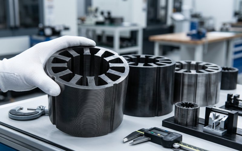
We stamp, stack, and ship motor lamination stacks for eVTOL propulsion systems. This is what we’ve learned about where designs break down—and where they hold.
Key Takeaways
- Cut-edge degradation on 0.20 mm silicon steel consumes 25–40% of a narrow stator tooth’s cross-section. Stress-relief annealing at 750–800°C recovers 20–30% of that core loss penalty (ring-core method, 1.0T/400Hz).
- Rotor bridges below 0.5 mm in 0.20 mm stock are achievable but not stable for production runs above ~2,000 pieces without accelerated die maintenance.
- Bonded stacks (backlack or adhesive) consistently outperform interlocked stacks on both eddy current loss and thermal conductivity in eVTOL-class power density motors.
- The stamped-condition bridge width is not the drawn bridge width. Rollover and burr shift the effective structural cross-section. Specify both on your drawing.
The motor on an eVTOL doesn’t get to coast. During hover, the battery dumps at 3–5C. The motor sees peak torque for 12–20 minutes straight, sometimes more during aborted approaches. Then it transitions to cruise, and the electromagnetic load profile changes completely. Then it goes back to hover for landing. Every flight is a thermal cycle that would be unremarkable in an industrial drive but is punishing at the power densities eVTOL requires.
We don’t design the motors. We build the lamination stacks that go inside them. But the problems land on our desk anyway, because the lamination is where electromagnetic intent meets manufacturing reality. A rotor bridge that passes FEA at 0.35 mm doesn’t necessarily survive 50,000 stamping cycles at that width. A stator tooth optimized for flux density at 12,000 RPM may not have enough material left after cut-edge degradation to carry the flux the model promised.
In eVTOL laminations, the real challenge isn’t just surviving 15,000 RPM—it’s surviving 15,000 RPM at 0.20 mm gauge while maintaining absolute thermal contact between every lamination in the stack.
This post covers the specific lamination challenges we see in eVTOL programs—not theory, but the trade-offs that surface when a customer sends us a DXF and we have to figure out how to actually make it work.
People assume the jump from automotive traction motors to eVTOL propulsion motors is incremental. It isn’t.
An automotive traction motor lamination can tolerate a few extra grams. It sits inside a housing bolted to a subframe. Cooling jackets surround it. The duty cycle includes long stretches of partial load. If core loss runs 5% above simulation, the thermal system absorbs it.
An eVTOL motor has none of that slack. Every gram of lamination steel is a gram the aircraft carries through every hover, every climb, every transition. The cooling path is constrained by fuselage packaging—sometimes it’s just airflow over the housing. And the duty cycle at hover is brutal: sustained full-power operation where any excess eddy current loss or hysteresis loss becomes heat with nowhere to go.
| Parameter | Automotive Traction Motor Lamination | eVTOL Propulsion Motor Lamination |
|---|---|---|
| Typical silicon steel thickness | 0.30–0.35 mm | 0.20–0.25 mm (some programs at 0.15 mm) |
| Core loss tolerance vs. simulation | ±8–10% acceptable | ±3–4% before thermal budget breaks |
| Rotor bridge minimum width | 0.8–1.2 mm | 0.4–0.7 mm (structural limit at RPM) |
| Stack weight sensitivity | Low–moderate | Every gram audited against flight envelope |
| Typical annual volume per SKU | 50K–500K+ | 200–5,000 (prototype through LRIP) |
| Post-stamping anneal requirement | Often skipped in high volume | Almost always required |
| Burr height limit | 25–40 µm | 10–20 µm, sometimes tighter |
| Joining method | Interlocking, welding common | Bonding (backlack or adhesive) preferred to avoid inter-laminar eddy current paths |
| Slot fill factor sensitivity | Moderate | High—every % of copper fill factor affects continuous thermal rating |
That volume column matters more than people think. At 200–5,000 units, you can’t amortize a progressive die the same way. Some of our eVTOL stacks run on compound dies or even wire EDM for prototype quantities. The economics of the stamping route feed back into what geometries are actually feasible at a given program phase.
Going thin reduces eddy current losses. Straightforward in theory. At 0.20 mm and below, we’re working with material that wants to deform under almost any mechanical contact.
The cut-edge damaged zone on a stamped lamination is roughly 0.3–0.5 mm deep on each side, depending on steel grade, die clearance, and tool sharpness. On a 0.35 mm automotive lamination with a 4 mm stator tooth, that damaged zone occupies maybe 15–25% of the tooth width. Manageable.
On a 0.20 mm eVTOL lamination with a 2.5 mm tooth, the same damaged zone eats 25–40% of the active cross-section. The permeability in that zone is degraded. Core loss is elevated. The tooth doesn’t carry flux the way the electromagnetic model expects—back-EMF waveforms shift, cogging torque increases slightly, and the efficiency map drifts from simulation.
Three things we’ve learned to manage this:
We run 5–7% of material thickness per side for eVTOL gauges, versus the 8–10% that’s common for thicker stock. This reduces the plastic deformation zone and shortens the burr-plus-rollover profile, but increases die wear. Tool life drops roughly 25–35%. We re-grind more often. That’s a cost the customer absorbs, but it’s better than absorbing a 15% core loss penalty across the full operating envelope.
On automotive programs, we sometimes ship un-annealed stacks when the customer’s thermal budget allows it. On eVTOL, we anneal almost everything. A controlled cycle at 750–800°C in a dry nitrogen/hydrogen atmosphere (dew point below −40°C) recovers most of the magnetic properties lost during stamping.
The numbers, measured on ring-core samples per IEC 60404-6 at 1.0T/400Hz: core loss reductions of 20–30% post-anneal on 0.20 mm material. Relative permeability at 1.0T recovers from as low as 2,500 (as-stamped) to 5,500–7,000 (annealed). That’s not a refinement—it’s the difference between a motor that meets its thermal target and one that doesn’t.
Some customers ask for laser-cut laminations assuming the cut quality is better. It can be—but the heat-affected zone from a fiber laser on thin silicon steel introduces its own magnetic degradation, sometimes comparable to stamping in terms of permeability loss within 0.2 mm of the edge. We use laser for prototypes, for geometries too complex for stamping, and for very low quantities where tooling cost doesn’t make sense. For production above ~500 stacks, a well-maintained stamping die still wins on edge quality at 0.20 mm, as long as the die clearance and maintenance schedule are right.
eVTOL motors—especially the direct-drive configurations used on tilt-rotor architectures—don’t always run at the extreme RPMs you’d see in a high-speed automotive motor. Some hover at 2,000–4,000 RPM. But the ones driving smaller propellers or running through a reduction stage can push 12,000–20,000 RPM, and the centrifugal stress on the rotor lamination at those speeds is real.
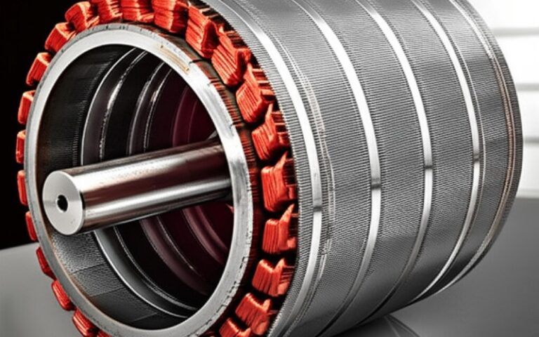
The rotor bridge is the thin section of steel between the magnet pocket and the rotor OD. It exists to retain the magnets against centrifugal force. Electromagnetically, you want it as thin as possible because it’s a leakage flux path—any flux that takes a shortcut through the bridge instead of crossing the air gap is wasted, reducing torque density and distorting the back-EMF waveform. Structurally, it has to survive centrifugal loading at maximum overspeed with a safety margin that satisfies aerospace-grade certification.
Here’s the tension: the electromagnetic designer wants a 0.3 mm bridge. The structural analyst says 0.6 mm minimum at 15,000 RPM with a 1.5× safety factor. The stamping engineer says anything below 0.5 mm in a progressive die at 0.20 mm stock thickness is going to be inconsistent after 10,000 hits.
One thing that rarely appears in simulation handoffs: the bridge width on the drawing is nominal. After stamping, the bridge has a burr on one side and a rollover on the other. The effective structural cross-section is not the same as the drawn dimension—it’s typically 0.03–0.08 mm less, depending on material and tool condition. We measure it. We report it. Most of our eVTOL customers now include a stamped-condition bridge width tolerance on their drawings, separate from the nominal design width. If yours doesn’t, it should.
We can’t name the customer. What we can share is the problem-solving sequence, because it illustrates how lamination manufacturing constraints feed back into motor design—not the other way around.
The program was a 130 kW direct-drive outer rotor motor for a multicopter configuration. Initial design spec: 0.20 mm non-oriented silicon steel, 48-slot stator, 40-pole rotor, max speed 3,200 RPM. The stator tooth width was 2.8 mm. Rotor bridge was drawn at 0.45 mm.
What happened at prototype: Core loss on the first batch of stator stacks measured 18% above the electromagnetic simulation (ring-core witness samples, 1.0T/400Hz, pre-anneal). After annealing, the gap closed to 6%—better, but still outside the ±4% thermal margin the customer’s cooling system could absorb. The rotor bridges on the first 50 pieces showed ±0.06 mm variation, which the structural analysis accepted, but the leakage flux variation was creating measurable cogging torque scatter between motors.
What we changed:
Result: Motor prototype testing showed continuous hover power within 2% of the thermal simulation target. The customer proceeded to LRIP (low-rate initial production) without redesigning the electromagnetic circuit.
This is a typical eVTOL engagement for us. The design intent is right. The first-pass manufacturing result isn’t quite there. The iteration happens in die clearance, process control, and inspection strategy—not in redesigning the motor.
The lamination stack is not just an electromagnetic component. It’s also a thermal pathway—often the primary conductive path for getting heat out of the stator windings and into whatever cooling system exists.
This creates requirements that sometimes conflict:
A loosely compressed stack has air gaps between laminations. Air is a thermal insulator. The tighter the stack, the better the layer-to-layer thermal path. But over-compression damages the insulation coating and creates inter-laminar short circuits, which increase eddy current losses, which creates more heat. We target a stacking factor of 95–97% for eVTOL stacks, which is on the high end of what we’d run for automotive. Getting there without damaging the coating requires controlled pressing with real-time force monitoring—we log force-displacement curves on every stack and flag anomalies automatically.
Interlocking creates local deformation at each dimple point, which disrupts the insulation layer and creates air pockets around the interlock feature. Each interlock point becomes a micro-source of both excess eddy current loss and thermal resistance. For eVTOL, most of our customers specify backlack (self-bonding coating) or adhesive bonding. The adhesive layer fills micro-gaps and actually improves thermal transfer between laminations while maintaining electrical insulation. The trade-off is cycle time and process complexity—bonding requires a controlled cure step (typically 180–200°C for 30–60 minutes under clamping pressure) that interlocking doesn’t.
This is technically the motor designer’s problem, but it lands on us because the slot shape we stamp determines how well the winding sits against the stator tooth wall—which directly affects copper fill factor and thermal coupling between conductor and iron.
A slot with tight radii and clean edges allows the winding to nest closer, reducing the air gap between copper and steel. A slot with burrs or rollover pushes the winding away from the wall, degrading the effective slot fill.
On an eVTOL motor running at continuous high power, that extra 0.1 mm of effective air gap between winding and tooth can mean 5–10°C higher winding hot-spot temperature. We’ve verified this in back-to-back thermal tests (thermocouple-instrumented motor, same winding process, same operating point) with one stack at 15 µm burr height and one at 30 µm. The difference was consistent and repeatable across three motor samples.
Most eVTOL programs we work with use radial flux permanent magnet synchronous motors. The lamination stack is a conventional cylindrical geometry—stator ring, rotor disc, stamped from flat sheet. We know how to make these. The tooling is understood. The stacking process is mature.
But axial flux motors are showing up more often. The torque density advantage—shorter axial length for the same torque output—is attractive for eVTOL packaging where axial space is constrained but radial space is available.
Axial flux laminations are a different animal. The flux path runs axially through the stack rather than radially, which means the lamination plane has to be oriented differently. Some axial flux designs use wound strips of silicon steel (tape-wound cores). Some use SMC (soft magnetic composite) powder cores. Some use segmented laminations arranged radially, like slices of a pie.
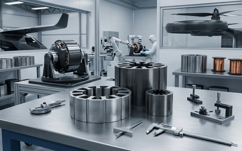
We produce segmented stator laminations for axial flux topologies. The stamping is straightforward—each segment is a small, relatively simple shape. The challenge is assembly: getting dozens of segments aligned, bonded, and compressed into a ring with consistent magnetic properties and tight geometric tolerance.
The hard part of axial flux laminations is not making the piece. It’s making the stack. A 0.05 mm misalignment between segments creates a local reluctance variation that disrupts flux distribution and creates a hot spot. Fixturing matters enormously. We use bonded assembly with custom alignment fixtures and verify concentricity on CMM after cure.
For axial flux rotors, laminations are less common—many designs use solid steel or SMC. When laminations are specified, they’re typically thin rings or annular shapes that require specialized blanking tooling.
This isn’t a catalog—it’s what we’ve built stacks from, measured, annealed, and shipped to customers who’ve put them in functional test motors.
| Material | Thickness | Core Loss (1.0T/400Hz, annealed) | Saturation ($B_{sat}$) | Stampability | Joining | Best Use Case | Key Limitation |
|---|---|---|---|---|---|---|---|
| Non-oriented Si-steel (~2.5% Si) | 0.20 mm | 1.8–2.2 W/kg | ~1.80 T | Good | Bonding or interlocking | Default eVTOL stator/rotor | Cut-edge degradation on narrow features |
| High-Si steel (~3.0–3.5% Si) | 0.15 mm | 1.2–1.6 W/kg | ~1.75 T | Difficult—brittle | Bonding only | High-RPM motors where eddy current loss dominates | Die life drops 30–40%; no interlocking possible |
| Amorphous/nanocrystalline ribbon | 0.020–0.025 mm | 0.3–0.5 W/kg | ~1.56 T | Not stampable conventionally | Bonding only | Ultra-low-loss applications, small cores | Requires etching or EDM; fragile; not volume-ready |
| Cobalt-iron (49% Co-Fe) | 0.10–0.20 mm | 1.0–1.5 W/kg | ~2.35 T | Stampable but abrasive | Bonding preferred | Maximum power density, minimum motor size | Material cost 15–30× silicon steel; hard on tooling |
If you’re optimizing for weight-per-kilowatt at the motor level, cobalt-iron gives you the smallest lamination stack for a given torque. If you’re optimizing for unit economics across a fleet, silicon steel at 0.20 mm is where most programs land. The decision usually gets made in the context of the full aircraft weight budget—sometimes a 200 g saving in the motor stack lets you add 200 g of battery, which changes the mission profile.
Automotive quality is ISO/IATF based. Aerospace quality for eVTOL motor components is evolving, but the trajectory is toward AS9100 and EASA/FAA Part 21 compliance. What our eVTOL customers currently require:
This is more documentation than most automotive programs. The volumes are lower, but the paperwork per part is heavier. We’ve built our quality system to handle it because we see this market growing and the requirements tightening as type certification programs move through the EASA/FAA process.
There isn’t a single standard. Most programs we support use 0.20 mm silicon steel as a baseline. Higher-RPM motors or programs with very tight loss budgets move to 0.15 mm or thinner. The choice is driven by the motor’s operating electrical frequency—thinner laminations reduce eddy current losses proportionally, and the payoff is larger at higher frequencies.
Technically yes, but we recommend against it for most eVTOL applications. Interlocking dimples create local insulation damage and inter-laminar short circuits between laminations, increasing eddy current losses. They also introduce thermal resistance at each dimple point. For a motor that’s already thermally constrained at continuous hover power, that combination is a problem. Bonding (backlack or adhesive) gives a cleaner electromagnetic and thermal result.
On thin-gauge material with narrow features—typical of eVTOL stator designs—the magnetically damaged zone from stamping can occupy 25–40% of a stator tooth width. This raises core loss, reduces effective permeability (which shifts back-EMF waveforms and increases cogging torque), and creates a discrepancy between FEA predictions and actual motor behavior. Stress-relief annealing recovers most of the damage. Without annealing, actual stack performance can deviate 15–25% from the simulation baseline.
Yes. We manufacture segmented stator laminations for axial flux topologies. The stamping per segment is standard; the assembly into a precision ring is where the difficulty concentrates. We use bonded assembly with custom fixturing to maintain segment-to-segment alignment within 0.05 mm and verify concentricity on CMM after cure.
The regulatory framework is still forming. Most of our eVTOL customers require AS9100-aligned quality management, full material traceability (heat number to stack serial), and lot-level core loss verification per IEC 60404. As type certification programs mature under EASA SC-VTOL and FAA Special Conditions, we expect requirements to formalize further—particularly around process change control and material qualification.
It depends on where you sit in the weight-vs-cost trade-off. Co-Fe alloys offer ~2.35 T saturation versus ~1.80 T for silicon steel, enabling a physically smaller motor for the same torque. The material costs 15–30× more. For programs where the aircraft’s payload margin is tight and every gram of motor mass directly reduces revenue payload, the math works. For urban air taxi platforms optimizing unit economics across a fleet, silicon steel usually wins.
Rough order of magnitude: wire EDM laminations cost 30–80× more per piece than progressive-die-stamped laminations at production volume. The breakeven depends on geometry complexity, but for most eVTOL stator designs, stamped tooling starts to make economic sense above 300–500 stacks. Below that, wire EDM or compound dies are more cost-effective when tooling amortization is included.
Same process discipline as high volume, applied to smaller lots. We run first-article and last-article inspections on every production batch. Core loss witness rings are tested from each coil of incoming steel. Stack dimensions are verified on CMM. The difference from automotive is that statistical process control alone doesn’t work when the lot size is 200 stacks—we inspect more, measure more, and document more per unit produced.
Struggling with rotor bridge deformation in your current prototypes? Seeing core loss numbers that don’t match your simulation? Send us your DXF file for a free DFM review—we’ll assess edge-degradation risk, bridge manufacturability, and thermal stack compression for your specific geometry and volume. No NDA required for initial review.