Let Sino's Lamination Stacks Empower Your Project!

To speed up your project, you can label Lamination Stacks with details such as tolerance, material, surface finish, whether or not oxidized insulation is required, quantity, and more.

Farad Core: decoding a confusing phrase—and how capacitors and magnetic cores actually work together

If you’ve ever seen “farad core” and wondered what on earth it means, you’re not alone. The phrase mashes up two different ideas from power electronics:

  • Farad → the unit that measures a capacitor’s ability to store electric charge.
  • Core → the magnetic core (often ferrite) used inside inductors and transformers.

Understanding how farads (capacitors) and cores (magnetics) work together is the real unlock—whether you’re tuning audio gear, building a DC/DC converter, or squeezing life from a tiny battery pack. Below, we untangle the terminology, ground it in solid references, then go beyond the basics with practical design notes you can use today.


  • What you’ll learn
    • What a farad really measures—and why supercapacitors are different from “normal” caps.
    • What a ferrite core is—and why designers obsess over permeability and core loss.
    • How caps + cores form the beating heart of power supplies, audio rigs, robotics, and EV subsystems.
    • How to pick parts (with rules-of-thumb), avoid common traps, and reason about lifetime and safety.

First, a quick disambiguation

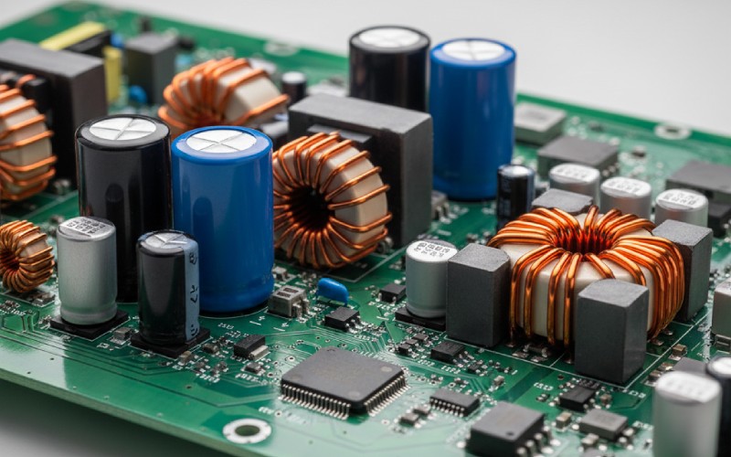
When someone says “farad core,” they usually mean either: (1) a large-value capacitor (measured in farads), or (2) a ferrite core used in inductors/transformers. They’re complementary parts of the same power path, but they’re not the same thing. Think of capacitors as your energy buffer and magnetic cores as your energy shuttle.


  • Pocket definitions
    • Capacitance (Farads): How much charge a capacitor can store per volt. Bigger F → more stored energy (E = ½ C V²).
    • Supercapacitor: A capacitor with farad-scale values (e.g., 100 F, 500 F), very low ESR, rapid charge/discharge, usually ~2.5–2.7 V per cell.
    • Ferrite core: A ceramic, iron-oxide-based magnetic core with high permeability and low electrical conductivity that reduces eddy currents, ideal for transformers/inductors.

How they fit in the same power story

In a buck converter, an inductor wound on a ferrite core shuttles energy between the input and output, while capacitors (measured in farads) smooth the ripples and act as reservoirs. The “farad-core stack” is what gives you clean, stable rails from noisy or intermittent sources.


  • Where you’ll meet this duo
    • Point-of-load regulators: CPUs, GPUs, FPGAs need rock-steady rails with fast transients.
    • Audio power: bulk caps for low-frequency energy + chokes/transformers for filtering/isolating.
    • Robotics & IoT: supercaps absorb motor inrush; inductors tame EMI and shape current.
    • Renewables & storage: supercaps buffer PV/wind variability; magnetics in DC/DC and isolation stages.
ferrite inductor with capacitors

Capacitors in farads: what’s realistic (and why it matters)

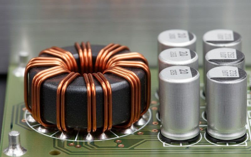
Modern supercapacitors are commonly rated around 2.5–2.7 V per cell, with very low ESR for fast bursts. Example parts include 100 F at 2.7 V and 630 F at 2.5 V devices—great for short-term energy buffering, peak-shaving, or brownout protection, but not energy-dense like batteries. Their sweet spot: seconds to minutes, not hours.


  • Supercap design notes you can apply
    • Voltage stacking: series cells need balancing (active or passive) to keep cell voltages safe.
    • Derating: keep operating voltage ~10–15% below the rated max for life and reliability.
    • ESR matters: lower ESR → cooler operation and higher peak current. Check datasheets, not just capacitance.
    • Lifetime & temp: many rated ~1,000 h at 65 °C—cooling and derating dramatically extend life.

Magnetic cores (ferrites): shaping current, starving noise

ferrite core provides high magnetic permeability with low conductivity, which cuts eddy currents and keeps losses down at switching frequencies. Material choice (and geometry) determines saturation flux density, core loss, and EMI behavior. Vendors like TDK publish families optimized for power vs. signal applications, making material selection a first-order design decision.


  • Picking a core the pragmatic way
    • Frequency first: choose material optimized for your switching frequency (e.g., 100–500 kHz).
    • Flux swing: size the core so your peak ripple current doesn’t push you into saturation.
    • Loss budget: balance copper vs. core loss; small cores run hot if you under-size.
    • EMI reality: common-mode chokes and beads are ferrite-based because they target high-freq noise with minimal DC loss.

Side-by-side: what “farads” and “cores” bring to the table

Use this to explain your choices to colleagues, or sanity-check your BOM.

DimensionCapacitors (measured in F)Ferrite Cores (inside inductors/transformers)
Primary roleStore/smooth energy, reduce voltage rippleTransfer/shape energy, limit ripple current, isolate
Governing physics(Q = C \cdot V), (E = \tfrac12 C V^2)Faraday’s law, (V = L \frac{di}{dt}); B-H curve & core losses
Typical single-cell limits~2.5–2.7 V for supercapsSaturation flux density sets current limit
Key performance leverESR (loss/heat), capacitance, leakagePermeability, core loss vs. frequency, saturation
Representative parts100 [email protected] V, 630 [email protected] V examples on the marketPEL/PC materials for power ferrites (vendor families)
Lifetime driversTemperature, voltage derating, ripple currentTemperature rise from copper & core loss, flux swing
Datasheet gotchas±30% tolerance is common on big supercapsLoss curves vs. frequency & flux density are essential
Where to startCapacitance from ripple & transient specInductance from ripple target; then check core loss

  • Quick calculator mindset
    • Energy needed? (E = \tfrac12 C V^2). Solve for C at your min voltage; don’t forget droop.
    • Ripple target? Pick L for current ripple, then back-solve for core size/material to avoid saturation & losses.
    • Thermals first: if it can’t shed heat, it won’t meet spec in the field.

ferrite cores and supercapacitor module

Real-world parts: what the market tells us

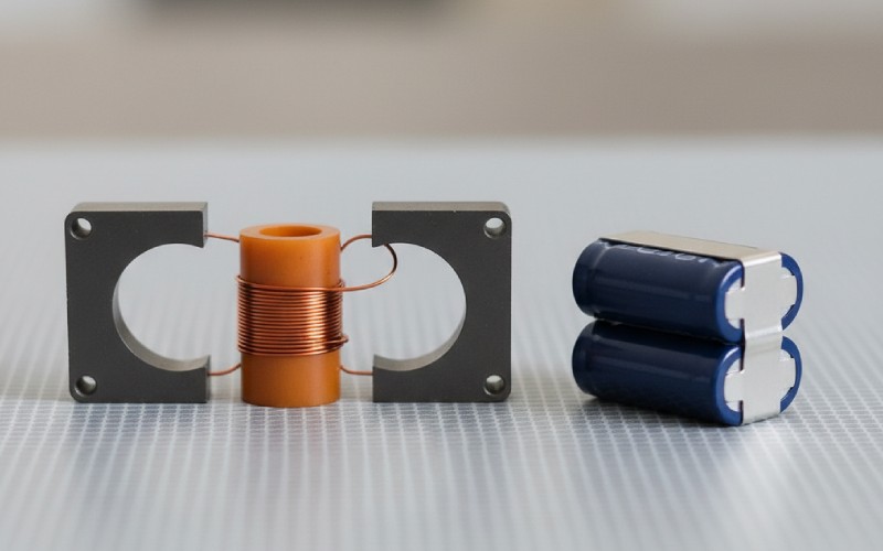
Browsing current listings shows hundreds-of-farads supercaps at low voltages (e.g., 630 F / 2.5 V can-style parts) and 2.7 V / 100 F options with explicit ESR and lifetime specs. On the magnetics side, vendors emphasize material selection (core losses vs. frequency) just as much as geometry, underscoring that “the core is the part.” These are the constraints that shape every serious power design.


  • Pitfalls that burn projects
    • Treating capacitance as the only knob; ESR and ripple current limits kill boards silently.
    • Ignoring balancing on series supercaps → one cell overvolts and dies early.
    • Selecting a ferrite by shape alone; material is a must-decide parameter.
    • Testing at room temp only; hot boxes tell the truth.

A note on names you might stumble across

You may also see “ferrite cores” on cables (snap-on beads) to choke high-frequency noise, and even “Farad” used as a brand or token name online (e.g., FRD). These are unrelated to the physics we’ve covered here—don’t let SEO confuse your design decisions.


  • If you’re spec’ing today, start here
    • Define transient (ΔI/Δt) and ripple targets; pick L first, then cores.
    • Size bulk and output capacitance for energy and ripple, then iterate ESR/ESL.
    • Check losses & thermals with your real switching frequency and duty cycle.
    • Validate EMI early with the actual harness/cabling (ferrites as needed).

Bottom line

There isn’t a single thing called a “farad core.” There are farads (capacitors) and cores (magnetics)—and modern electronics demand that you get both right. Treat them as a pair: caps buffercores shape. If you size, derate, and thermally manage them together, your power rails will be calmer, your EMI will be kinder, and your products will feel… effortless.

Share your love
Charlie
Charlie

Cheney is a dedicated Senior Application Engineer at Sino, with a strong passion for precision manufacturing. He holds a background in Mechanical Engineering and possesses extensive hands-on manufacturing experience. At Sino, Cheney focuses on optimizing lamination stack manufacturing processes and applying innovative techniques to achieve high-quality lamination stack products.

New Product Brochure

Please enter your email address below and we will send you the latest brochure!

en_USEnglish

Let Sino's Lamination Stacks Empower Your Project!

To speed up your project, you can label Lamination Stacks with details such as tolerance, material, surface finish, whether or not oxidized insulation is required, quantity, and more.