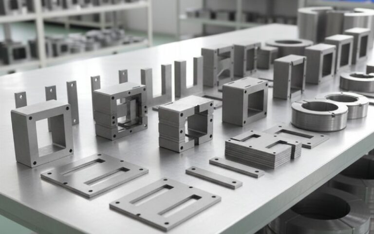
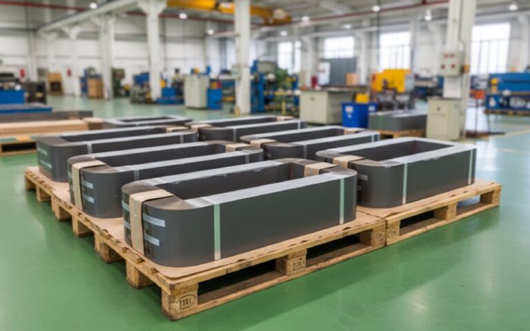
Let Sino's Lamination Stacks Empower Your Project!
To speed up your project, you can label Lamination Stacks with details such as tolerance, material, surface finish, whether or not oxidized insulation is required, quantity, and more.
Ferrite Cores: The Little Black “Mystery Bulges” That Quiet Your Electronics
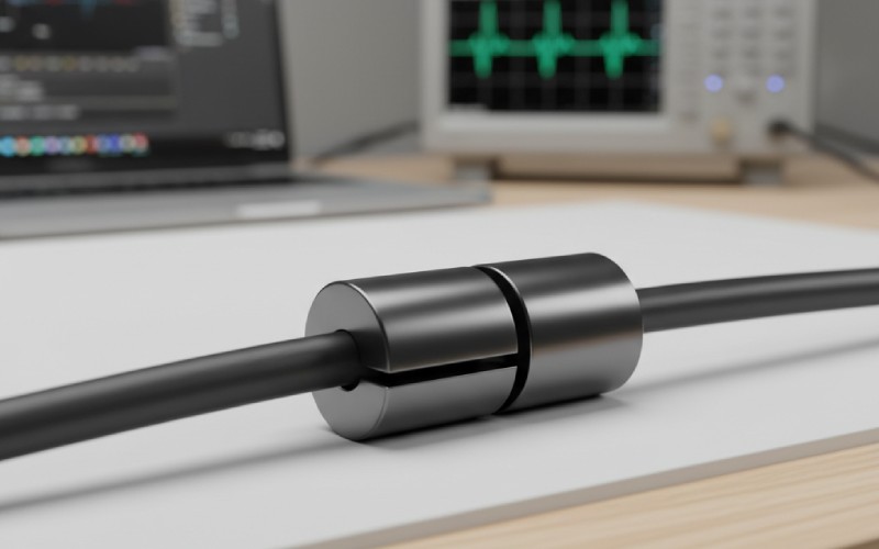
If you’ve ever noticed a weird black “pill” on your laptop charger, monitor cable, or USB lead… you’ve already met a ferrite core.
It’s one of those components that quietly saves your day: it doesn’t blink, click, or get hot, but it can be the difference between a rock-solid design and a miserable EMI failure at the test lab. Ferrite cores are where physics, materials science, and very practical engineering all shake hands.
In this guide, we’ll go beyond the usual “it blocks noise” explanation and build a real mental model of how ferrite cores work, when they help, and how to choose the right one without guesswork.
Short on time? Here’s the TL;DR
Ferrite cores are magnetic “jackets” made of ceramic-like material that add high impedance to high-frequency noise, while barely affecting low-frequency power or signals.
Inside, they’re made from soft ferrites (usually MnZn or NiZn blends) tuned for specific frequency ranges and applications.
Clip-on cable cores are perfect for quick EMI fixes in the field; beads and toroids are better for designed-in PCB and power solutions.
Picking the right core is about matching material + shape + impedance curve to the frequency band of your noise.
Used well, ferrites can save you a redesign. Used blindly, they can do nothing—or even make ringing and EMI worse.
Table of Contents
What is a Ferrite Core, Really?
At its heart, a ferrite core is a magnetic core made of ferrite: a ceramic compound of iron oxide mixed with metals such as manganese, zinc, or nickel. These are called soft ferrites, meaning their magnetization can reverse easily, with low energy loss.
Two properties make them special:
High magnetic permeability – they strongly guide magnetic flux, so a wire passing through them sees a much higher inductance than it would in air.
High electrical resistivity – unlike metal cores, ferrites don’t let big eddy currents circulate inside. That means less loss and better behavior at higher frequencies.
Day to day, this shows up in two broad families of use:
As cores in inductors and transformers (power supplies, RF transformers, antennas).
As EMI suppression components on cables and PCB traces (clamp-on cores, beads, sleeves, rings).
Instead of thinking of ferrite as “a black rock,” think of it as a tunable magnetic sponge for high-frequency energy.
Ferrite cores vs other core materials (fast comparison)
Laminated steel / powdered iron: great for low-frequency power (50–400 Hz, maybe tens of kHz) but too lossy or inductive behavior breaks down at higher frequencies.
Soft ferrite (MnZn, NiZn): sweet spot from tens of kHz up into the hundreds of MHz, depending on mix—ideal for SMPS transformers, RF inductors, and EMI suppression.
Hard ferrite (permanent magnets): used for speakers and motors, not for cores in inductors or EMI clamps.
Air core: perfect linearity, no saturation—but very low inductance, so you need many turns and big coils.
How Ferrite Cores Tame Noise (Intuitive Mental Model)
Let’s build a picture you can carry in your head.
Imagine your cable as a water pipe. Your desired signal or DC power is a slow, steady flow. High-frequency noise and RF interference are like turbulent ripples and tiny waves riding on top.
A ferrite core wrapped around that cable behaves like:
A gentle restriction for the slow, steady flow (low-frequency current): barely any effect.
A very rough, lossy sponge for the fast ripples (high-frequency currents): it adds impedance, absorbs energy, and turns it into tiny amounts of heat instead of letting it radiate as EMI.
Electrically, here’s what’s going on:
At low frequencies, the core acts mostly like an inductor: the impedance is small and largely reactive.
As frequency rises, core losses increase; the impedance becomes more resistive, which is good because resistive impedance dissipates noise power instead of storing and re-emitting it.
This is why datasheets for ferrite beads and cores always show a Z vs frequency curve: you want the peak of that impedance to overlap with the frequency band of your unwanted noise.
Where you’ve already met ferrite cores in real life
The small bulge near the end of your laptop charger cable or monitor cable.
Clip-on cylinders installers add to HDMI, USB, or audio cables to fix interference issues.
The black SMD “beads” scattered all over modern PCBs on power rails and high-speed signals.
Toroid rings and E-cores inside switch-mode power supplies and DC-DC converters.
Ferrite rod antennas inside AM radios and RFID tags.
Ferrite Materials: MnZn vs NiZn (and Why You Should Care)
Not all ferrites are created equal. Manufacturers blend materials to target different frequency bands and loss behaviors. The two big families used in cores and EMI parts are:
MnZn (Manganese-Zinc) ferrites
NiZn (Nickel-Zinc) ferrites
MnZn tends to have higher permeability and saturation flux, which is great for lower frequencies (power magnetics, SMPS transformers). NiZn tends to have higher resistivity and is better suited for higher-frequency applications (RF, broadband EMI suppression), though with lower μ.
Below is a simplified comparison to anchor your intuition:
Material
Typical Useful Frequency (EMI / signal use)
Key Traits
Typical Uses
MnZn
~10 kHz – a few MHz (up to ~5 MHz in many apps)
High permeability, lower resistivity, strong inductance at lower freq
SMPS transformers (tens–hundreds of kHz), common-mode chokes on mains input, low-MHz noise suppression
NiZn
~1 MHz – hundreds of MHz
Lower μ, higher resistivity, wideband high-frequency loss, less effect at low freq
Clamp-on cable cores for digital cables, RF chokes, PCB ferrite beads for >10 MHz noise
Special “EMI mix” ferrites
Tuned peaks (e.g., AM band, VHF, GSM bands, etc.)
Engineered loss peaks (μ″) around specific bands
Automotive EMI parts, communication equipment, band-targeted suppression parts
Quick rule-of-thumb for material choice
Noise mainly below ~5 MHz (e.g., switching ripple, SMPS edges, motor drives)? → Start with MnZn-based cores.
Noise mainly above ~10–20 MHz (USB, HDMI, RF hash, digital edges)? → Look at NiZn-based cable cores and ferrite beads.
Trying to solve a regulatory EMI failure? → Check the test report, find the problem frequencies, and choose ferrite material whose impedance peak overlaps that band.
Shapes: Beads, Cores, Chokes, and Clamps
Once you’ve picked a material family, the next question is shape. The shape determines not just mechanical fit, but how much inductance and impedance you can generate for a given cable or number of turns.
Common shapes include:
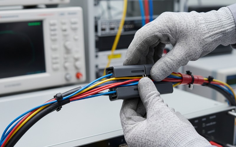
Cable clamp / clip-on core – split ferrite inside a plastic housing, snaps around an existing cable. Perfect for retrofit or last-minute EMI fixes.
Toroid (ring) cores – continuous ring of ferrite that you wind wires through; great for common-mode chokes and power inductors.
E-cores / U-cores / RM-cores – interlocking shapes used to build power transformers and inductors with bobbins.
Ferrite beads (SMD / through-hole) – small cylinders or blocks that a single conductor passes through; on PCBs, they look like resistors or small black chips.
Sleeve / tube cores – ferrite cylinders that you slide a wire or bundle through, often used for cable suppression or as cores in simple inductors.
Behind the scenes, many vendors talk about shape factor (the ratio of core dimensions) because it influences how much impedance you can get per turn and how the core saturates and heats.
Shape to use when…
You can’t change the cable and need a field-installable fix → clip-on / clamp-type ferrite core.
You’re designing a common-mode choke for mains or DC input → toroid or dedicated choke core, usually MnZn.
You want to clean up noise on a single PCB net (e.g., VDD, USB shield, RF feed) → SMD ferrite bead with the right Z vs f curve.
You have a flat ribbon or flex cable → flat ferrite clamp or flexible strip ferrite.
A Practical Selection Flow (For Cables and PCBs)
Here’s how experienced EMC engineers usually approach ferrite selection—not by rummaging through the junk box and hoping, but by matching physics to the problem.
Identify the “bad” frequency band. Use EMI test results, scope with current probe, or even regulatory lab feedback. Are the peaks at 30–50 MHz? 150–300 MHz? Around 1 MHz?
Decide: common-mode vs differential-mode noise.
Common-mode: the same noise current on all conductors, relative to chassis/ground. Cable ferrites excel here.
Differential-mode: noise between two conductors; better attacked with LC filters, proper layout, or common-mode chokes rather than just a clamp near the connector.
Pick material and impedance curve.
Use manufacturer datasheets and selection guides (Murata, TDK, Laird, etc.) to find parts with high impedance at your problem frequencies.
Size the core. Make sure the inner diameter fits your cable or number of turns, and check that current + temperature won’t push the core into saturation or excessive heating.
Prototype and measure. Add the ferrite, retest EMI or ringings. Adjust turns, placement, or material as needed. Sometimes a smaller core in the right place beats a huge clamp that’s too far from the source.
Ferrite core selection checklist
[ ] Note the frequency band(s) where you fail EMI or see ringing.
[ ] Decide if the noise is common-mode (cable shield, all conductors together) or differential-mode (between two conductors).
[ ] Choose MnZn vs NiZn (or special mix) aligned to that band.
[ ] Use vendor curves to pick impedance at the problem frequency, not just at “100 MHz” by habit.
[ ] Check inner diameter, length, and number of turns you can physically route.
[ ] Validate current rating and temperature range (especially for power cables and automotive).
[ ] Prototype, measure, and iterate—don’t treat ferrites as magical decorations.
Installing Ferrite Cores on Cables (Without Guessing)
For many people, ferrites first show up as a field fix: “The radio is noisy; slap a clamp on the cable.” That can work—but it’s even more effective when you understand a few practical rules.
Key points from cable ferrite vendors and EMC specialists:
Put the ferrite as close to the noise source or to the device entry point as possible. For example, near the equipment connector, not halfway along the cable.
Running the cable through the core multiple times (forming a small coil) greatly increases common-mode impedance, roughly proportional to turns squared (N²).
For thick cables, multiple smaller cores can sometimes be more effective and flexible than one huge clamp.
Remember: on a multi-wire cable, the ferrite is mostly acting on common-mode current—the noise that flows in all conductors together relative to the environment—not on your differential signal. That’s why you can often add clamp cores without killing valid data.
Common mistakes when adding ferrite cores
Clamping only the shield drain wire instead of the entire cable bundle—this often does almost nothing.
Placing cores far from the device enclosure, where the cable has already radiated a bunch of energy.
Using a random cheap clamp with unknown material whose impedance peak doesn’t match your noise band.
Expecting a single ferrite to fix fundamental layout or grounding issues on the PCB.
Forgetting that too much ferrite on a high-speed link can distort edges and degrade signal integrity.
Under the Hood: A Slightly Deeper Physics Peek
If you like going one layer deeper, ferrite behavior is often described in terms of complex permeability:
μ′ (mu-prime): the energy-storing part (inductance).
μ″ (mu-double-prime): the lossy part (resistance, loss tangent).
EMI suppression ferrites are intentionally designed with a large μ″ in the target frequency band, so they become highly lossy there—exactly what we want for damping.
On a B-H curve, these materials behave as magnetically soft: you can swing the magnetic field back and forth with small hysteresis loss. That’s why they’re excellent for transformers and chokes where fields reverse every cycle.
But they’re not invincible:
Push too much DC current and you saturate the core, reducing incremental inductance and making the ferrite far less effective.
At some point, temperature also matters—both because ferrites have temperature-dependent permeability and because losses generate heat.
In other words, a ferrite bead or core is not just “a resistor at high frequency.” It’s a non-linear, frequency- and current-dependent component whose behavior you want to understand at least qualitatively.
Situations where ferrite cores aren’t the right tool
Fixing ground loops or 50/60 Hz hum in audio: that’s better handled by proper grounding, isolation transformers, or balanced signaling.
Cleaning up massive switching spikes caused by bad snubbing or no flyback diode—you need proper switching and layout fixes first.
Solving DC voltage droop or current limiting—ferrites are not regulators.
Handling very low-frequency EMI (<10 kHz); ferrites have limited impedance there and other filter types work better.
Quick FAQ
“If I just clip on random ferrites, will it hurt anything?” Usually not, especially on low-speed or power cables—but it might do nothing, or in rare cases affect edge rates on high-speed signals. Choose parts with known impedance curves.
“Do I need more than one core on a cable?” Sometimes yes. Two modest cores near the device end can outperform one large core mid-cable, especially if you can loop the cable through them for extra turns.
“What’s the difference between a ferrite bead and an inductor?” A ferrite bead is designed to behave lossy in a certain band (Z becomes largely resistive), whereas an inductor is designed to be as low-loss and reactive as possible. That’s why beads are great for damping, not just blocking.
“Can I fix an EMI test failure by adding ferrites at the last minute?” Often yes—many real-world fixes involve clip-on cores near connectors or swapping in better-chosen beads. But if the issue comes from fundamental PCB layout or enclosure problems, ferrites are more like band-aids than surgery.
Cheney is a dedicated Senior Application Engineer at Sino, with a strong passion for precision manufacturing. He holds a background in Mechanical Engineering and possesses extensive hands-on manufacturing experience. At Sino, Cheney focuses on optimizing lamination stack manufacturing processes and applying innovative techniques to achieve high-quality lamination stack products.
New Product Brochure
Please enter your email address below and we will send you the latest brochure!
Let Sino's Lamination Stacks Empower Your Project!
To speed up your project, you can label Lamination Stacks with details such as tolerance, material, surface finish, whether or not oxidized insulation is required, quantity, and more.