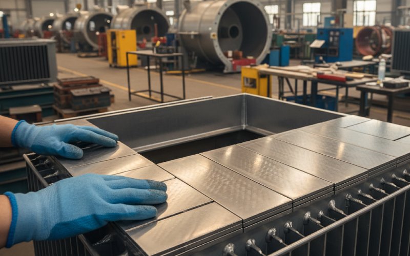
Let Sino's Lamination Stacks Empower Your Project!
To speed up your project, you can label Lamination Stacks with details such as tolerance, material, surface finish, whether or not oxidized insulation is required, quantity, and more.
Grain orientation is where transformer efficiency quietly hits its ceiling. Align it well and modern CRGO lets you squeeze no-load loss into the sub-watt-per-kilogram range; let the flux wander twenty or thirty degrees off and you give a big chunk of that margin back as heat.
Most datasheets package grain orientation into two friendly lines: B₈ around 1.9–2.0 T and core loss numbers near 0.7–0.9 W/kg at 1.5 T, 50 Hz for thin Hi-B grades. Design texts then say “keep flux along rolling direction” and move on. Useful, but very compressed.
In practice, that “direction” is the biggest hidden variable in your no-load loss budget. Grain-oriented steels are engineered so that permeability and loss are strongly anisotropic: flux along rolling direction sees low coercivity and high permeability; flux that rotates away pays a rising penalty. Modern reviews of electrical steels still show a clear gap between grain-oriented and non-oriented steels, but with performance deteriorating progressively as the magnetization angle drifts from rolling direction.
Transformer manufacturers know this, even if they rarely spell it out. When they estimate core loss from steel curves, they already apply a “design” or “weighting” factor to cover joints, corner regions and off-axis flux. That factor is basically your penalty for how well (or badly) you respect grain orientation inside the assembled core.
On paper, CRGO is a polycrystal with a very sharp Goss texture, {110}〈001〉 mostly locked to rolling direction. In reality, every grain is a little off. Deviation angles of a few degrees are common, and they vary from grain to grain. Under a uniform magnetizing field along rolling direction, domains in the “best aligned” grains move freely; domains in misaligned grains need more field, flip less cooperatively, and waste more energy each cycle.
As soon as you magnetize at an angle to rolling direction, you load more of those harder grains. Magnetic measurements on ultra-thin grain-oriented steels show that saturation flux density and permeability drop steadily with magnetization angle, with a sharp deterioration beyond about 20–30 degrees. Classic angular studies on conventional GO show the same story: loss and permeability curves are roughly symmetric around rolling direction and specific core loss at 1.5 T can almost double between 0° and around 60–90°.
That is why “about 30 degrees” keeps popping up in modern anisotropy work. Within that range GO still beats non-oriented steel for flux density and loss. Beyond that, the benefit shrinks rapidly and can effectively vanish at higher flux or frequency.
To put this into something design-friendly, you can treat the angle as a multiplier on your steel datasheet rather than a footnote.
The table below compresses trends from several angular-dependence studies into a simple relative view. It is not a substitute for your own Epstein measurements; it is a rough map of what published anisotropy curves already imply.
| Magnetization angle to rolling direction | Relative saturation flux density B_sat / B_sat(0°) | Relative specific core loss P / P(0°) | Practical comment |
|---|---|---|---|
| 0° (rolling direction) | 1.00 | 1.0 | What the datasheet actually describes. |
| 10° | ≈0.98 | ~1.1 | Generally within noise for many designs, still very close to ideal. |
| 20° | ≈0.95 | ~1.3 | Noticeable increase in no-load loss at high induction; still clearly better than non-oriented. |
| 30° | ~0.90 | ~1.5–1.7 | Often quoted as the practical limit where GO retains clear advantage; joints and yokes can sit here if flux is modest. |
| 45° | ~0.80 | ~2.0 | Typical of poorly designed corners or miscut segments; GO benefit mostly eaten. |
| 90° (transverse) | ~0.75 | ≥2.0 | Material behaves closer to a mediocre non-oriented sheet than to premium GO. |
Again, these numbers are indicative. Grades, thickness, stress state and induction level move them around, but the shape of the trend is persistent.
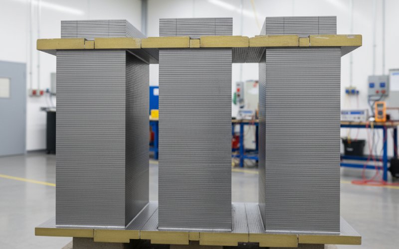
On the drawing, your three-phase core looks perfectly aligned. In the stack, it is not.
Straight limbs cut with rolling direction parallel to flux are as good as the material will ever be. Once you reach joints and corners, the flux has to curve. Even with mitered or step-lap joints, there are small regions where the local flux direction cuts through the laminations at 30–60 degrees. That is where the penalty from the previous table hides.
Recent anisotropy work on grain-oriented cores with layers shifted by a constant angle shows measurable changes in total core loss just from changing how laminations in a stack are angularly misaligned with each other. Similar investigations on Fe–Si GO sheets confirm that total loss is a mix of isotropic eddy-current loss and strongly directional hysteresis plus excess losses, all swinging with magnetization angle.
Design software often models GO with a simple permeability tensor built from just rolling and transverse curves, interpolated elliptically. That treats transverse as the worst direction and assumes everything between behaves smoothly. More detailed measurements at multiple angles show that this shortcut can give noticeable error, especially at higher flux levels where anisotropy becomes more nonlinear. You feel that as the gap between predicted and measured no-load losses on new designs.
So any region of the core where flux lines have complicated 2D trajectories — step-lap overlaps, T-joint regions, corner zones of wound cores — should mentally be tagged as “off-axis loss multipliers”, not just geometric details.
Orientation is not only an angle on your CAD model; the steel’s stress state and domain pattern modify it.
Producers of Hi-B grades like ORIENTCORE show that tensile stress along rolling direction, induced primarily by the surface coating, can reduce hysteresis and eddy losses and at the same time shrink magnetostriction, which helps both efficiency and noise. There is an optimum region: too little stress and domains are not stabilized; too much and losses climb again.
Laser scribing and other domain-refinement techniques work by subdividing domains along rolling direction without wrecking the coating. Measurements on 3% Si–Fe show meaningful reductions in core loss after such treatment, provided magnetization is close to rolling direction. Once flux starts to rotate, those carefully formed narrow domains are not used as efficiently.
Cutting does the opposite. Mechanical punching introduces plastically deformed edge zones with residual stresses and local misorientation. That effectively thickens the off-axis shell of each lamination, especially in thin ultra-low-loss grades. Winding or assembling cores with poor control over gap pressure or uneven clamping adds further stress states that do not line up neatly with the intended flux direction. None of that shows up in the steel mill’s grade label, but it all changes the effective anisotropy you see in the finished transformer.
Magnetostriction quietly connects back to orientation as well. Data for grain-oriented steels show magnetostriction amplitude depends both on material grade and on the angle between magnetization and rolling direction. Misaligned joints not only waste energy; they also become local noise sources.
Most core design flows still treat grain orientation as a binary choice: use CRGO, align laminations, done. With current efficiency expectations and energy prices, that is a very coarse approach.
A more useful mindset is to treat angle as a limited resource you allocate.
High-flux regions — central limbs, main yokes, tank-side zones where induction is pushed close to 1.7–1.8 T — deserve magnetization angles as close to 0° as layout allows. Joint regions can tolerate more deviation if local flux density is reduced by geometry, but once you let those regions live around 30° at high flux, you are sitting in the row of the table where your loss multiplier approaches 1.5 or above.
Material studies that compare grain-oriented and non-oriented steels over 0–90° confirm what designers already suspected: GO keeps a strong advantage within roughly 20–30°, and then its superiority fades quickly. So if you are designing something where flux will routinely see 45–60° in large regions, it is worth asking whether a premium GO grade is the right cost choice at all, or whether geometry should change instead.
Manufacturing tolerances fit into the same mental model. A slitting process that leaves a few degrees uncertainty in the effective rolling direction on individual strips may be acceptable in low-flux yokes, but becomes expensive if those strips migrate into limbs. Good core builders already segregate coils and lamination sets by measured loss and directionality; design engineers should assume that behaviour, not ideal material, when they size their loss margins.
Numbers make this less abstract. Take a 1 MVA distribution transformer with a modern Hi-B core. Using contemporary GO grades around 0.23–0.27 mm, you can target no-load losses near 800–1000 W at nominal induction, according to typical grade tables.
Now assume your core design and manufacturing choices effectively push the average magnetization angle in a fraction of the core from “almost perfect” into the 20–30° band. The table earlier suggests a plausible 30–50% increase in specific loss in those regions at the same flux density. Suppose the net effect is a conservative 20% rise in total no-load loss: an extra 160–200 W.
Over a 25-year life, with the transformer energized most of the time, that extra 200 W quietly burns around 44 MWh. Even at modest energy prices, that is several thousand in operating cost that achieved nothing except feeding anisotropy the wrong way. Scale that to a fleet of thousands of units and the columns on your loss-capitalization spreadsheet start to look different.
The key point is that this cost is not “material grade” cost; it is orientation cost. You already paid for the good steel.
The lab side is catching up to what designers need. Conventional Epstein frame tests at 0° and 90° still form the backbone of grade certification, but there is now a lot more work on multi-angle characterization and modelling of anisotropy. Instead of feeding the solver two curves and interpolating, you can build models based on measurements at three or more cutting angles and predict properties for arbitrary angles with better fidelity.
Non-destructive methods like magnetic Barkhausen noise are also being used to classify grain-oriented steels and infer texture quality and stress without full magnetic testing, and interestingly their angular dependence lines up with the idea that properties remain fairly flat up to a certain angle window before degrading. That gives you tools to audit whether the coil that just arrived at your plant has the sharp texture and low stress state you designed for.
On running transformers, you obviously cannot put the core back into an Epstein frame. But you can still monitor harmonic content of magnetizing current, temperature patterns on joints, and noise signatures around corners as indirect evidence of where orientation is being wasted.
A lot of the recent work on grain-oriented steels is actually driven by motors, not transformers. Engineers are experimenting with segmented stators where each segment keeps its flux within that favourable ±20–30° window and gains a few percent torque or efficiency compared to non-oriented cores.(PMC) That is just another expression of the same anisotropy you fight in transformer joints.
Ultra-thin GO, higher-silicon alloys and advanced coatings continue to push core losses down under ideal alignment. But as the intrinsic material losses shrink, the share of loss coming from orientation mistakes, cutting damage and assembly stress gets larger. The relative importance of design and manufacturing discipline grows even if the absolute watts fall.
So the practical takeaway is simple, even if execution is messy. Grain orientation is not a slogan; it is a scarce asset. You select it when you choose CRGO, then you either protect it with good geometry, tight cutting, careful stress control and realistic modelling, or you trade pieces of it away in corners and joints. The transformer does not care whether the extra watts came from a cheaper grade or a sloppy angle; it only knows the magnetization path it actually sees.