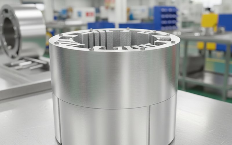
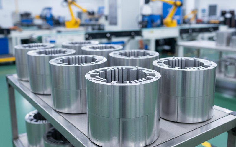
Let Sino's Lamination Stacks Empower Your Project!
To speed up your project, you can label Lamination Stacks with details such as tolerance, material, surface finish, whether or not oxidized insulation is required, quantity, and more.
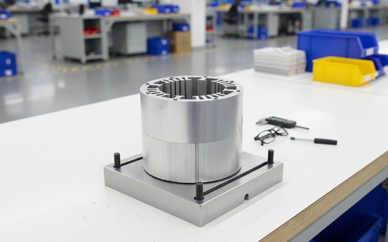
Most comparisons between hairpin winding and round wire stop at copper fill. That is too early. The real split starts in the lamination stack: slot opening, liner shape, burr sensitivity, insertion path, end-edge condition, and how much process variation the stack can absorb before yield starts slipping. Hairpin usually buys higher slot fill, shorter end windings, and a more compact copper package. Round wire usually buys more winding freedom and a stack that forgives more. Those are not marketing differences. They are tooling, scrap, and lifetime differences.
When we review a new stator program, we do not ask “flat wire or round wire?” first. We ask what the lamination stack must survive. Sharp slot edges, liner wrinkling, slot mouth accessibility, local springback during insertion, phase separation inside the slot, and later, PWM-driven insulation stress. The winding choice changes all of them.
With round wire, the stack is usually more tolerant of geometric drift. The conductor is smaller, more compliant, easier to guide, easier to redistribute in the slot. With hairpin, the conductor shape starts dictating the slot. Corners matter more. Stack straightness matters more. Slot-to-slot repeatability matters more. A lamination stack that is technically “within drawing” can still be a poor stack for flat wire if the liner folds badly, if the tooth-tip edge marks the enamel, or if the slot mouth gives just enough access for one production batch and not the next.
That is why a switch from round wire to hairpin is rarely a wire-only change. It is usually a slot architecture change. In many flat-wire stators, axial insertion becomes attractive and the insulation arrangement shifts toward more complete enclosure of the conductor inside the slot. In round wire stators, U-shaped slot paper and a later slot closure are common because the winding is drawn into the slot from the stator inner side and can share the slot with separators where phase management requires it.
Hairpin likes copper density. The lamination stack pays for it.
Typical distributed round-wire builds often sit around a lower slot fill range than rectangular conductors, while rectangular wire commonly pushes into roughly the 0.6 to 0.7 band, and some advanced flat-wire routes go higher still. That higher fill is real. But it only matters if the slot geometry, insulation package, and insertion method can hold it without chewing up enamel or forcing unstable compaction at the tooth tips.
For classic round wire, engineers can often keep more freedom in slot opening and turn count. For traditional layered hairpin, turn-count flexibility is tighter, and certain layouts naturally fall into even-turn constraints. So the lamination stack is not just sized around copper area; it is sized around feasible layer count, crossover logic, and joining geometry outside the stack. That narrows the design window, a bit, then a lot.
There is another twist. In some continuous flat-wire process routes, the stack needs a radially open slot and access near conductor width plus a small clearance margin for insertion. That can push the slot opening wider than an electromagnetic designer would prefer. Wider openings may slightly worsen eddy-current behavior, cogging, and noise behavior if the rest of the design is not adjusted. So the lamination stack becomes a negotiation between manufacturing access and magnetic cleanliness.
On flat-wire programs, we treat slot insulation as part of the stack design, not a later consumable. The liner is doing several jobs at once: ground insulation against the steel, abrasion protection during insertion, conductor separation, overlap control, and sometimes slot closure logic. Current production surveys show O-shaped liner arrangements are common in flat-wire stators because they keep the phases separated from the lamination stack around more of the conductor perimeter. B-shaped concepts can add conductor-to-conductor protection, but they cost copper space and are harder to automate cleanly. Round wire more often lives with U-shaped slot insulation plus phase separators where needed.
That means the lamination supplier cannot look only at tooth width and stack length. End-edge quality matters. Slot wall texture matters. Corner radius consistency matters. On flat wire, a small defect at the axial end of the stack can become a repeatable liner-cutting point. Process studies on slot insulation for flat-wire stators flag end-edge damage, cracks, wrinkles, air pockets, and paper position drift as real quality features, not cosmetic ones.
Every stator stack needs burr control. Hairpin just makes the penalty steeper.
With round wire, the conductor bundle and liner system can absorb more local irregularity before damage appears. Not unlimited. More forgiving, yes. With hairpin, the conductor face is broader, stiffer, and less willing to route around a local edge defect. In production terms, slot burr, die roll, and end-face sharpness stop being inspection data and become a yield predictor. The same is true for stack compression quality: if the slot throat varies because the stack is not sitting as one clean body, the insertion force stops being stable. Then insulation damage becomes random. Random damage is expensive.
For our lamination stacks, this usually changes the approval logic. We care less about nominal dimensions printed in isolation and more about the slot as a formed path: entry edge, wall straightness, tooth root, end-edge, and what the liner sees during motion. That is the stack the winding team actually buys.
Hairpin does bring a real thermal and DC-resistance advantage in many designs because more copper sits where the slot can reject heat and because end windings can be shorter. But flat conductors also pay more AC loss at higher electrical frequency if the conductor section is too large or the slot layering is chosen badly. One established mitigation is to increase conductor layers and reduce individual conductor height or section so skin and proximity effects ease off. That is not a winding-only fix. It feeds straight back into lamination stack slot proportions and insulation packaging.
So a flat-wire stack should not be sold on fill factor alone. A deep, narrow slot that helps split the conductor section may improve high-frequency loss behavior, but it also tightens liner forming and raises sensitivity to slot straightness. A wider, shallower slot may be easier to manufacture, then it punishes AC loss. There is no universal “best slot” here. Only a stack matched to the drive cycle and the real production route.
Hairpin programs often carry many weld points or joints. That adds process complexity and can affect reliability if insulation is stressed during forming, stripping, twisting, or welding. So even though the weld sits beyond the active lamination length, the stack still feels it indirectly: the straighter and more consistent the conductor exit from the stack, the less compensation the joining station needs, and the lower the chance of loading the insulation system before the electrical test station ever sees it.
This is one reason we prefer to discuss the lamination stack, the liner, and the winding route in one design review. Separate teams create hidden cost. Usually not on day one. Later.
| Design point | Round wire winding | Hairpin / flat wire winding | What it means for lamination stacks |
|---|---|---|---|
| Typical slot fill behavior | Lower, often around 0.35–0.45 in many distributed builds | Higher, often around 0.6–0.7; advanced flat-wire routes can go higher | Flat wire pushes harder on slot utilization, but stack quality must support the fill without liner or enamel damage |
| Insertion logic | Commonly drawn into the slot from the stator inner side | Often axial insertion for standard hairpin; some continuous routes require radial access | Slot opening, tooth-tip design, and stack accessibility depend on the process route |
| Slot insulation style | U-shaped liner and optional phase separators are common | O-shaped liner is widely favored; extra conductor separation schemes trade off fill factor | Liner geometry becomes a first-order stack feature in flat wire |
| Tolerance sensitivity | More forgiving | Less forgiving | Burrs, end-edge sharpness, slot straightness, and stack compression matter more with flat wire |
| Electrical tradeoff | More winding freedom, smaller conductors help AC-loss behavior | Better DC packing and thermal path, but high-frequency AC loss can rise if conductor section is too large | Slot proportions must balance manufacturability and frequency loss |
| Design freedom | High turn-count flexibility | Traditional layouts can restrict turn-count options | Stack design is more tightly coupled to winding-layer feasibility |
We usually revise five things early.
First, slot entry geometry. Not just width. The lead-in condition. Hairpin does not like a mathematically acceptable but mechanically sharp tooth tip. Second, liner allowance. The slot has to fit copper plus insulation plus process reality, not copper plus wishful CAD. Third, axial end-face condition. Flat wire programs are less tolerant of rough stack ends and liner scuffing during insertion. Fourth, slot depth-to-width ratio. That choice controls both AC-loss exposure and manufacturability. Fifth, stack joining and retention. Any local distortion that changes slot form is now more expensive than it looked during lamination quoting.
If the program stays with round wire, our stack review shifts. We care more about winding freedom, wedge or cover-slide compatibility, separator placement, and how much slot geometry margin the coil insertion process will need. The electromagnetic package may accept shapes that a flat-wire process would reject quickly. That is one quiet advantage of round wire. It keeps more of the lamination stack design space open.
No. Hairpin is often better for copper utilization and compact packaging, but it also makes the stack more sensitive to slot geometry, liner execution, and insertion damage. If the program has high electrical frequency, aggressive slot-mouth constraints, or weak control of end-edge quality, round wire can be the more stable stack choice.
Sometimes for a prototype, rarely without compromise for production. Slot opening strategy, insulation shape, corner condition, and layer feasibility usually need rework. Reusing the old stack often leaves the flat-wire winding carrying the consequences.
Not the copper. The hidden risk is stack-process mismatch: a slot that looks acceptable in CAD but damages liner or enamel during insertion, then produces intermittent insulation failures or unstable yield.
No. Higher slot fill can reduce DC copper loss and help compactness, but once conductor section, slot shape, and frequency move out of balance, AC loss and process damage can erase the gain. Better fill is only better when the stack and winding route were designed together.
Because the liner is carrying more risk. It protects against the sharp-edged lamination stack during assembly and operation, controls conductor separation, and has to survive higher insertion precision demands with less room for wrinkles, cracks, or overlap drift.
The short version, though not the simple one: hairpin winding changes the lamination stack from a magnetic part into a magnetic-and-process part. If that shift is designed in early, flat wire can be excellent. If not, round wire keeps winning in places nobody planned to measure.