Let Sino's Lamination Stacks Empower Your Project!

To speed up your project, you can label Lamination Stacks with details such as tolerance, material, surface finish, whether or not oxidized insulation is required, quantity, and more.

Root Causes of Localized Hot Spots Near Lamination Joints

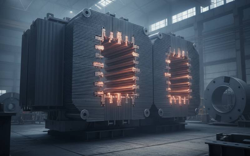
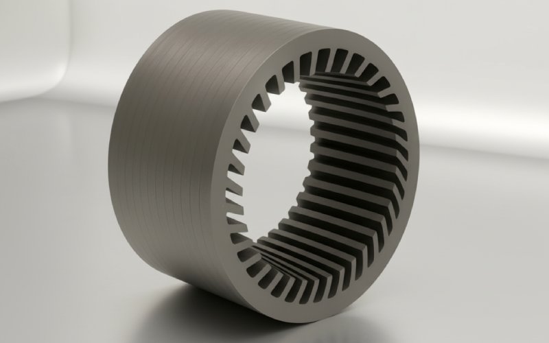
When a transformer or generator runs, the first place many experienced engineers look for trouble is the core joints. Those sneaky lamination joints — T-joints, mitred corners, step-laps — are where flux changes direction, gaps are hardest to control, and where local “mystery” hot spots love to appear on thermography.

In this article we’ll walk through why those hot spots happen, how to tell the “harmless warm patch” from a genuine core fault, and what design, manufacturing and O&M practices actually prevent them — not just on paper, but in the field.


  • Who is this for?
    • Design engineers working on laminated cores (transformers, reactors, generators, large motors)
    • Test & commissioning engineers trying to explain infrared or core test anomalies
    • Asset managers deciding whether a hot spot is a “monitor” or “shut it down” situation
    • Maintenance teams planning inspections, EL CID / core loop tests, or internal overhauls

1. Why lamination joints are natural hot-spot magnets

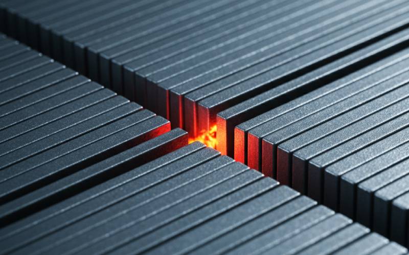
At a lamination joint, the magnetic flux is being forced to turn a corner and jump from one stack of steel to another. In three-phase transformer T-joints, several limb fluxes even add up in one shared region, which pushes local flux density above the average in the core.

Research on distribution transformer cores shows that localized losses at certain T-joint regions can be significantly higher than the average core loss, especially near inner edges of butt joints where flux crowding and unfavorable flux angles occur. That extra loss turns directly into heat — so your IR camera “sees” a hot spot even when nameplate load is fine.


  • At a high level, hot spots near joints usually come from some combination of:
    • Flux crowding & local saturation where flux density spikes at corners, T-joints, or poorly designed step-laps
    • Inter-lamination shorts from burrs, scratches, warped laminations, or damaged coating creating eddy-current loops
    • Extra reluctance or air gaps at joints due to misalignment or poor stacking, forcing flux to “detour” and concentrate in narrow regions
    • Stray flux & circulating currents from multi-point core grounding, leakage flux, or structural parts soaking up flux near the joint
    • Cooling problems (blocked ducts, stagnant oil/air pockets) that turn a moderately higher loss region into a genuine thermal risk
    • Harmonics, over-excitation and DC bias that drive core regions (especially joints) closer to saturation, blowing up iron loss and temperature

2. The physics under the hot spot (without drowning in math)

Before we blame manufacturing or maintenance, it helps to visualize what the physics is doing at a joint. In a perfect laminated core:

  • Flux mostly flows along the rolling direction of the grain-oriented steel
  • Laminations are insulated from each other so eddy currents stay tiny and confined
  • Joints are arranged so flux crosses from one limb to another gently, not violently

Reality is messier. At a T-joint or mitred corner:

  1. Flux turns and spreads. The flux vector rotates away from the easy rolling direction and may even develop components perpendicular to the lamination plane. That raises hysteresis loss and eddy currents in that region.
  2. Normal flux crosses laminations. Where laminations overlap (step-laps, butt-joints), a “normal” component of flux tries to go through the stack, not just along it. That encourages eddy-current loops through multiple sheets instead of just one — a perfect recipe for local heating.
  3. Any defect multiplies the effect. Burrs, extra gaps, or shorted laminations distort the local reluctance, pushing even more flux into already stressed steel. In measured cores, localized loss at inner regions of T-joints has been observed to rise significantly above outer regions at the same overall flux density.

So even if nameplate losses look fine, joints are where physics makes the margin thinnest — which is why that’s where defects show up first as hot spots.


  • Key physical mechanisms that turn lamination joints into hot spots:
    • Flux angle effects: Flux deviating from rolling direction > higher hysteresis loss in CRGO steel
    • Normal flux component: Through-thickness flux > multi-lamination eddy currents instead of single-sheet
    • Local saturation: Crowding at corners & T-joints > B peaks above design > steep rise in iron loss
    • Inter-lamination shorts: Lost insulation or debris bridging laminations > “solid core” behavior in that pocket
    • Leakage flux capture: Structural parts or clamps near joints pick up stray flux and heat locally
close-up lamination joint hotspot

3. A practical root-cause map (what’s really behind those hot spots?)

Let’s connect the physics to things you actually see during manufacturing, testing, or operation.

Below is a compact “field map” of the most common root causes behind localized hot spots near lamination joints, and how they tend to show up.

Root cause categoryMechanism at lamination jointField clues you seeTypical fix / prevention
Flux crowding & joint designPoor T-joint / corner design, insufficient overlap, or step-lap geometry causing local B peaks and unfavorable flux anglesRepeatable hot spot at the same joint on multiple units of the same design; temperature scales strongly with voltage (V/Hz)Re-optimize joint geometry (step-lap, mitre angle, overlap length), reduce operating flux density, improve FEM modeling of core joints
Lamination shorts / damaged coatingBurrs, scratches, warped plates or missing coating create inter-lamination conductive paths; region behaves like a thicker solid plateLocalized hot spot that may grow over time; EL CID / core test shows localized high signal; sometimes metallic sheen or discoloration inside coreTight burr control, deburring, controlled punching; maintain coating integrity; core-back grinding and inspection; reject or rework damaged stacks
Misaligned or gapped jointsPoor stacking, uneven step-laps, extra air gap along butt-joint; flux forced into narrow “bridges” with higher B and normal flux componentHot band along a joint rather than a single point; no major change in global core loss but abnormal local temperatureBetter stack fixtures & automation, consistent bolt torque, magnetic gap fillers, improved dimensional tolerances on laminations
Multi-point core groundingCirculating currents in core due to more than one ground point; currents concentrate near joints & structural contactsElevated core grounding current (>100 mA), DGA thermal gases, hot streaks near core clamps or lead exitsEnforce strict single-point core grounding, inspect and remove unintended grounds, consider temporary series resistor while planning outage
Stray flux in structural partsLeakage flux at joints and ends inducing eddy currents in clamps, tie plates, tank wall, etc.Hot spot not exactly on core but on clamp/tank near joint; tends to worsen at higher load / currentAdd magnetic shunts, copper shields, or flux diverters; relocate or redesign metallic pieces near high-flux areas
Cooling & oil/air flow issuesBlocked ducts, stagnant oil pockets near top yoke or limbs; a slightly higher-loss joint region overheats because it can’t shed heatTemperature rise much higher than expected for a modest increase in loss; IR shows broader warmer zonesClean and verify cooling ducts, maintain oil quality and level, ensure forced cooling equipment works as intended
Harmonics, over-excitation, DC biasNon-sinusoidal flux and elevated V/Hz push joints closer to saturation; iron loss spikes at high-B regions firstHot spots appear during abnormal grid conditions, harmonic injection, or overfluxing events; trend correlates with V/Hz and THDEnforce V/Hz limits, install over-excitation protection, reduce harmonic injection (filters, STATCOM tuning)
Foreign objects & contaminationLoose metal particles or tools bridging laminations or laminations to grounded structure, often trapped near joints or ductsVery localized intense spot, sometimes intermittent; may move slightly, or appear after transport or overhaulStrict cleanliness, tool & material control, internal inspection during major outages, oil filtration and flushing where appropriate

  • How to use this map in real life:
    • Start with where the spot is: exactly at T-joint inner edge, on clamp, on tank, along a seam?
    • Look at how it scales: with voltage (flux), current (load), or both?
    • Combine that with test data (core loss, EL CID / loop test, DGA, grounding current) to narrow it from “something is warm” to “this is very likely misaligned step-lap / multi-point ground / lamination short”.

Some hot spots are not mistakes; they’re baked into the design margins. If you’re designing or specifying cores, you’re playing with these levers every day — sometimes without seeing the thermal consequences until later.

Well-documented studies on three-phase transformer cores show that T-joint regions are the most complex, loss-influential parts of the core: flux turns sharply, multiple limb fluxes superimpose, and both in-plane and normal flux components become large. Optimized joint designs (e.g., improved step-lap or mixed 60°/45° joints) measurably reduce localized loss compared with older 45°/90° arrangements.

Similarly, high-grade CRGO with proper coating and stress-relief annealing dramatically reduces both global and local core loss for a given B, which gives you more margin before joints run hot in service.


  • Design choices that strongly influence hot spots at joints:
    • Joint geometry:
      • Step-lap vs butt-joint vs mitred corner
      • Length & sequence of steps; overlap patterns in T-joints
    • Flux density / V/Hz:
      • Running “aggressively” close to the knee of the B-H curve leaves little margin at joints
    • Material selection:
      • Grade of CRGO, coating type, lamination thickness (thinner sheets = lower eddy currents)
    • Magneto-structural layout:
      • Location of clamping structures, tie-plates, tank proximity to core ends
      • Presence (or absence) of magnetic shunts / flux shields near joints
    • Cooling design around joints:
      • Duct layout near yokes and limb junctions; oil/air paths that actually wash past the hottest steel

5. Manufacturing & assembly: where “paper design” meets reality

Even a beautifully modeled core can misbehave thermally if manufacturing and assembly don’t treat lamination joints with respect.

Punching and stacking operations can leave burrs, warped plates, or misaligned step-laps. Industry experience and technical literature both note that scratches, large burrs, or warped laminations in the core stack can locally short laminations and cause local overheating, even when total core loss remains within spec.

On large machines (generators, big motors), lamination damage from vibration or loose cores can also wear away interlaminar insulation; worn insulation leads to shorts, core hot spots, and in extreme cases, melted cavities in the core if left unchecked.


  • Manufacturing / assembly issues that often become joint hot spots later:
    • Poor burr control and deburring: Rough edges increase risk of inter-lamination shorts and local flux distortion
    • Inconsistent stacking pressure: Loose stacks vibrate; over-tightened stacks squeeze out coatings or warp plates
    • Misaligned step-laps / T-joints: Manual stacking without proper fixtures or automation leads to erratic overlap and air gaps
    • Damaged coating at joints: Handling damage, scraping, or grinding without recoating creates conductive bridges
    • Foreign metallic debris: Welding slag, wire offcuts, tools, nuts/bolts trapped near joints or cooling ducts
    • Inconsistent clamp bolt torques: Uneven compression creates local gaps and paths for leakage flux and vibration

6. Operating conditions that “light up” joint weaknesses

You can inherit a perfectly built core and still get localized hot spots if the operating environment pushes it outside its comfort zone.

Over-excitation (high V/Hz), heavy harmonic content, or DC bias pushes flux density up, and the first places to complain are the joints and corners where B is already higher. Technical guidance on transformer cores highlights overload, increased iron loss from off-design operating points, and harmonics as important drivers of core overheating.

Stray flux is another culprit: leakage flux that escapes the main core — especially near winding ends and joints — can induce eddy currents in clamps, tank walls, and other metal parts, creating local hot spots that show up near joints even if the laminations themselves are okay.

Finally, multi-point core grounding is a classic “invisible” problem: two or more core grounds form a loop, circulating current in the core steel and structural path. That circulating current generates localized overheating detectable via infrared, grounding current measurements, and DGA gas signatures.


  • Operating scenarios that often trigger or worsen joint hot spots:
    • Prolonged operation at elevated V/Hz (underfrequency, overvoltage, generator step-up transformers during grid events)
    • High harmonic loading from converters, arc furnaces, or poorly filtered drives
    • Unbalanced or asymmetrical loading that distorts flux distribution and increases stray flux near joints
    • Multi-point grounding faults in transformer cores or stator cores
    • Cooling system degradation: clogged air/oil ducts, failed fans/pumps, thickened oil at low temperatures
    • Repeated through-faults or inrush events that mechanically stress the core and joints over time

engineer scanning transformer hotspot

7. How to diagnose localized hot spots near lamination joints

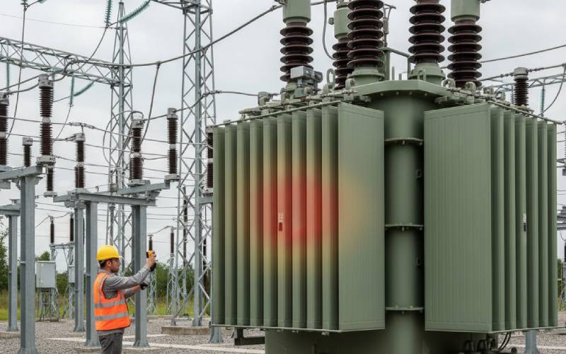
Once you’ve spotted a hot spot on an IR camera or from a thermal sensor, the real question is: is this an acceptable warm region, an early warning, or a genuine core fault in the making?

The best answers combine thermal observations with electrical and chemical tests. Modern research and field practice emphasize localized loss measurement, advanced thermography, and core fault detection techniques (like EL CID for generators or core loop tests for transformers) to pinpoint inter-lamination problems early.


  • A practical, layered diagnostic approach:
    • 1. Map the temperature pattern
      • Is the hot spot:
        • small, intense point? (think debris, lamination short, multi-point ground)
        • band along a joint? (likely design/assembly geometry or air gap)
        • On a clamp or tank near the joint? (stray flux in structural parts)
    • 2. Correlate with operating conditions
      • Does temperature track voltage (V/Hz) more than load current? → core issue
      • Does it track current / load more? → stray flux in structures or combined effects
    • 3. Run electrical tests
      • No-load loss & magnetizing current vs factory values
      • Core grounding current and insulation resistance (search for multi-point grounding)
      • Core fault tests (EL CID, low-flux loop tests) on large generators and big transformers to localize inter-lamination faults
    • 4. Use chemistry & gas analysis (for oil-filled units)
      • DGA: look for patterns consistent with thermal faults at moderate temperatures (hot metal / hot oil, typically <700°C)
    • 5. Decide on intervention level
      • “Monitor only” (slight design warm spot, stable over time)
      • “Plan outage and inspect” (abnormal but stable, some margin left)
      • “Urgent shutdown & internal inspection” (rising trend, abnormal tests, or evidence of core fault)

8. Prevention: design, factory, and field habits that actually work

Most localized hot spots at lamination joints are preventable with a mix of good design discipline, serious manufacturing QA, and realistic operational controls.

Think of prevention in three layers: (1) Design it right, (2) Build it clean, (3) Operate it kindly.


  • Design it right
    • Choose optimized joint geometries (step-lap, improved T-joints) validated with 2D/3D EM + loss simulations, especially in regions where multiple flux paths meet
    • Run cores conservatively on the B–H curve, leaving margin at joints instead of squeezing every watt out of iron loss
    • Specify high-grade CRGO, suitable coatings, and lamination thickness matched to frequency and loss targets
    • Place clamps, tie-plates, and tank walls with stray flux and eddy-current losses in mind; add shunts or shields where necessary
    • Design robust cooling paths at top yokes, limb junctions, and core ends
  • Build it clean
    • Enforce burr limits and deburring standards on lamination punching and cutting
    • Use automated or well-guided stacking for joints and step-laps to ensure overlap and alignment
    • Protect coatings during handling; repair or reject damaged plates, especially near joints
    • Apply strict foreign object control: tool/accountability systems, cleaning and inspection before closing the tank
    • Control clamp bolt torques and compression sequences to avoid uneven gaps and movement
  • Operate it kindly
    • Enforce V/Hz and harmonic limits with proper protection and system studies
    • Monitor core grounding current and insulation resistance to catch multi-point grounding early
    • Trend no-load losses, magnetizing current, and IR thermography on a consistent basis, not just once in a while
    • Keep cooling systems healthy: clean ducts, working fans/pumps, good oil condition, especially before peak loading seasons
    • Plan core inspections / EL CID at major overhauls for large machines and critical transformers

9. Bringing it together

Localized hot spots near lamination joints are not random bad luck. They’re almost always the visible tip of one or more underlying issues:

  • local flux behavior at joints,
  • the way we cut, stack, clamp and insulate steel, and
  • how the system pushes that core in real service.

When you combine thermal patterns with design knowledge and a few targeted tests, “that odd warm patch on the top yoke” turns into a clear story: misaligned step-lap, or lamination short, or multi-point ground, or stray flux in a clamp. And once you have that story, the path to mitigation — redesign, re-stack, re-ground, re-cool — becomes much clearer.

Share your love
Charlie
Charlie

Cheney is a dedicated Senior Application Engineer at Sino, with a strong passion for precision manufacturing. He holds a background in Mechanical Engineering and possesses extensive hands-on manufacturing experience. At Sino, Cheney focuses on optimizing lamination stack manufacturing processes and applying innovative techniques to achieve high-quality lamination stack products.

New Product Brochure

Please enter your email address below and we will send you the latest brochure!

en_USEnglish

Let Sino's Lamination Stacks Empower Your Project!

To speed up your project, you can label Lamination Stacks with details such as tolerance, material, surface finish, whether or not oxidized insulation is required, quantity, and more.