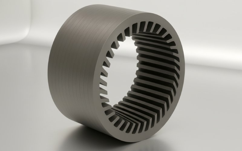
Let Sino's Lamination Stacks Empower Your Project!
To speed up your project, you can label Lamination Stacks with details such as tolerance, material, surface finish, whether or not oxidized insulation is required, quantity, and more.
The circle diagram of an induction motor might seem hard to understand. But it is really just a simple picture. This picture tells you all about your motor. It is a tool that uses a drawing. It helps you see how the motor will work. You don’t have to do hard math. This article will show you how to draw this helpful diagram. We will go step by step. You will learn what facts you need. You will also learn how to use these facts to see how well your motor works. Reading this will save you time. It will make a tricky subject easy to learn.
A circle diagram of an induction motor is a picture. It shows how an induction motor acts or works. You can think of it like a map for your motor. This one diagram can tell you many things. It can tell you about the motor’s current, power factor, efficiency, and torque. It shows this for any amount of load. It all begins with the motor’s equivalent circuit. As the motor’s slip changes, the tip of the line showing the stator current draws a path. This path makes a circle.
This picture, the circle diagram is a graphical drawing that shows the motor’s whole story. It shows how the motor uses power from the power line. You can see every detail, from no load at all to a full load. It is a very strong tool for engineers and people who fix machines. It helps them look at the performance of a machine. They can do this without needing to run a lot of different tests.
Learning how to make the construction of the circle diagram is very helpful. You can use simple shapes and lines instead of hard math problems. This makes it simple to see how the motor works. You can find the most output power or the most torque the motor can make. This information is very important. It helps you use the motor in the correct way.
This diagram helps you check the performance of a machine. You can quickly find the motor’s efficiency at a specific load. You can also see the power factor and how it changes. This helps make sure the motor is running well and not wasting power. It gives you a full picture of all the operating conditions of the motor. And it’s all on one piece of paper.
To draw the circle diagram, you first require some facts. You do not need to run the motor under every kind of load. Instead, you just need to do two simple tests. You also need to know the resistance of the stator winding.
Here is what you will need:
These three sets of facts are all you need to build the whole diagram.
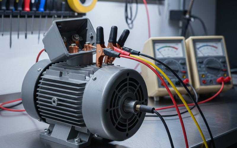
To obtain the findings from the no-load test, you run the induction motor at its planned voltage and frequency. You do this with no load. The motor will run at a speed that is very close to its synchronous speed. While the motor is running, you have to measure three things.
You will measure:
With this data, you can figure out the no-load power factor. You can find this by using the formula for power. The power you measure here is used to feed the constant loss in the machine. This includes things like friction, air resistance, and core loss. This gives us the first important point we need to begin drawing our diagram.
The second test is the blocked rotor test. For this test, you stop the rotor from spinning. You hold it still. The rotor is not moving, so this is like a condition of the biggest possible slip. We do not use the full voltage. Using full voltage would pull a very large current and could hurt the motor. Instead, we use a smaller voltage. We slowly turn up this small voltage until the normal full-load current is flowing in the stator.
During this test, you will measure:
The power you measure here is mostly the copper loss in the wires because the motor is not spinning. This blocked rotor test gives us the second important point for our circle diagram. The data must be adjusted for the motor’s normal working voltage.
Now you have the data, so you can start the construction of the circle diagram. Follow these easy steps to draw the circle.
The circle itself shows the total current the motor can pull. But we want to know about power and torque. To do this, we must add a few more lines to our diagram. These lines help us split up the different kinds of power and loss.
First, drop a perpendicular line straight down from point A to the flat base line. Let’s name the meeting point G. The line AG shows the total power going into the machine during the blocked rotor test. This power is made up of stator copper loss and rotor copper loss. We can split these losses. At a point F on the line AG, we can divide the line. AF will show rotor copper loss, and FG will show stator copper loss.
The output line is the line that connects O’ and F. This line is very important. The second important line is the torque line. This is the same as the output line. The torque the motor creates is related to the vertical distance from any working point on the circle down to this torque line.
One of the greatest things about the circle diagram of an induction motor is how simply you can find the biggest values. To find the maximum output power, you need to find the point on the circle. This point should be the farthest away from the output line O’F.
To do this, draw a line that runs next to the output line O’F. This new line should just barely touch the edge of the circle. The point where this new line touches the circle is the point of maximum output power. To find out how much power this is, draw a vertical line from this point down to the output line. The length of this line, changed back using your power scale, gives you the most output power the machine can make.
| Thing to Find | How to Find It on the Diagram |
|---|---|
| Maximum Output Power | The longest vertical line from the circle to the output line. |
| Maximum Torque | The longest vertical line from the circle to the torque line. |
| Maximum Input Power | The longest vertical line from the circle to the base line. |
The circle diagram is packed with helpful information. After you pick a working point P on the circle, you can find out many things about the motor’s performance at that exact load.
The final result is a total picture of your induction motor. The circle diagram of induction motor shows you the connection between all the important things: current, power, power factor, speed, torque, and efficiency. You can see how one thing changes when another thing changes. For example, you can see how the current and power factor move when you put more load on the motor.
This single tool, in the form of a picture, takes the place of many hard calculations. It makes the way the machine works clear and simple to understand. From just two easy tests, you can figure out the motor’s entire range of performance. It is proof of how a simple shape, a circle, can explain the detailed workings of an electrical machine. This is why the diagram of an induction motor is so important in electrical engineering.