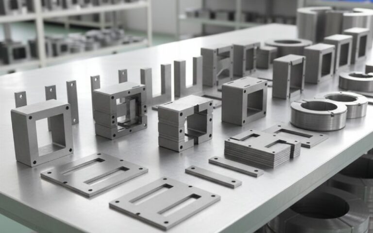
Let Sino's Lamination Stacks Empower Your Project!
To speed up your project, you can label Lamination Stacks with details such as tolerance, material, surface finish, whether or not oxidized insulation is required, quantity, and more.
How to Test an Armature with a Multimeter (The Clear, No-Nonsense Guide)
If your drill, vacuum, or saw lost torque, sparks more than usual, or just stopped dead, the armature could be the culprit. The good news: you can diagnose most armature problems with a multimeter and a few simple checks—no expensive growler required.
Below is the method I use in the field to quickly confirm whether an armature is healthy, borderline, or bad. It’s practical, step-by-step, and designed to help you avoid the common pitfalls that trip people up.
Table of Contents
TL;DR (Quick Start)
Unplug the tool and remove the armature.
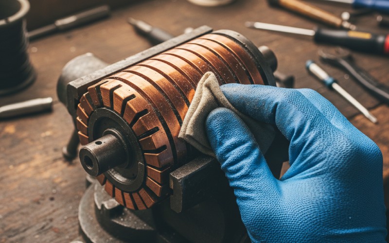
Clean the commutator and number the bars.
Check for:
Uniform low resistance between adjacent bars (within about 10% of each other).
No continuity (open circuit) between any bar and the shaft/core (i.e., not shorted to ground).
No opens between adjacent bars.
If one or more readings deviate significantly or you find continuity to the shaft, the armature is bad.
What Exactly Are We Testing?
An armature (in DC and universal motors) is the rotating part with a copper commutator. Winding coils connect to commutator segments (“bars”). Brushes ride on the commutator to feed current into the coils. A healthy armature has:
Very low, consistent resistance between adjacent commutator bars.
No electrical connection between any commutator bar and the shaft/laminations (the iron core).
A smooth, clean commutator surface and intact mica undercutting.
Note: Induction motors (like many AC fan motors) don’t have a commutator and aren’t tested this way.
Safety First
Unplug the tool and remove the battery. Let capacitors discharge.
Remove the armature from the tool to isolate it from the field windings and electronics.
Wear eye protection; copper dust and chips are no joke.
Don’t spin up the armature with external power unless you know what you’re doing.
Tools You’ll Need
Digital multimeter (DMM) with a reliable low-ohms range and continuity/beep function
Sharp tip probes or alligator clips; Kelvin clips if you have them
Scotch-Brite or very fine sandpaper (600–1000 grit) for commutator cleaning
Isopropyl alcohol and lint-free wipes
A fine marker to number segments
Optional but great: a current-limited bench supply (0.5–2 A), a micrometer, a magnifier
Pro tip: If your DMM has a Relative/Zero function, use it to cancel out probe and lead resistance.
Prep the Armature
Clean the commutator: Lightly burnish with fine abrasive, wipe with alcohol. Don’t gouge the copper.
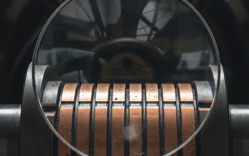
Inspect the commutator:
Look for dark, evenly colored copper. Deep burns, raised segments, or heavy grooving are red flags.
Check mica undercut (the insulating groove between bars). It should be slightly under the copper surface.
Number the bars: Put a tiny dot of marker on bar 1, then number around the circumference. This makes interpreting measurements way easier.
The Tests (In Order)
1) Visual and Mechanical Check
Commutator should be round, with no loose or lifted bars.
Windings shouldn’t be charred or slung out due to centrifugal force.
Shaft should be straight; bearings should spin smoothly.
If it fails here (cracked or lifted bars, badly burned comm), the meter is only going to confirm what you already see.
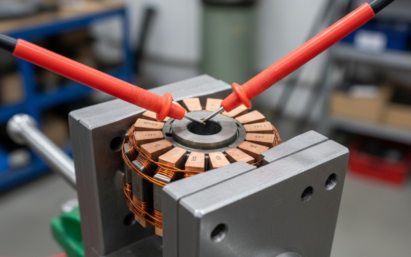
2) Quick Continuity Between Adjacent Bars
Meter: Continuity/beep mode or low-ohms.
Touch one probe to bar 1, the other to bar 2 (adjacent). Move around the commutator: bar 2–3, 3–4, etc.
What to expect:
You should get continuity (low resistance) between each pair of adjacent bars.
No reading (open circuit) between two adjacent bars usually means an open coil.
Important: Beep mode alone is not enough because the resistance is very small and beep thresholds are crude. Switch to ohms measurement next.
3) Bar-to-Bar Resistance Uniformity (The Most Telling Test)
Meter: Lowest ohms range. Zero out your leads if possible (Relative/Zero button).
Measure the resistance between each adjacent pair of bars all the way around (1–2, 2–3, …, N–1–N, N–1).
Record each value.
Typical results:
Absolute resistance will be very low (often 0.1–2.0 Ω depending on motor size). Your meter might show only a few tenths of an ohm.
The key is uniformity. All readings should be within about ±10% of each other. Tighter is better.
What failures look like:
One pair much lower than the rest: likely a shorted turn in that coil.
One pair much higher or open: broken coil or broken connection at the commutator.
Field tip:
Scrub the probe tips a little on each bar to cut through oxide. Poor contact causes false “high” readings.
If your DMM struggles with low-ohm accuracy, use the Voltage Drop Method below.
4) Ground Test (Bar to Shaft/Core)
Meter: High ohms/megohms range.
Touch one probe to the steel shaft or the laminated core; touch the other to each commutator bar in turn.
Expected:
Open circuit (very high resistance) on every bar. No bar should show measurable continuity to the shaft/core.
If you see continuity or low resistance to the shaft:
The winding insulation is compromised. That’s a grounded armature—replace or rewind.
Note: A proper insulation tester (megohmmeter at 250–500 V) is best for this, but a DMM can still catch gross grounds.
5) Optional: Voltage Drop Method for Better Sensitivity
If your meter can’t resolve tiny ohms differences accurately:
Set a bench supply to a safe, low voltage and current-limit it to ~0.5–2 A (depending on armature size).
Connect the supply across two adjacent bars (1–2) and let the current flow.
Measure the millivolts across the same bars with your DMM.
Move around the commutator and repeat.
Interpretation:
At constant current, voltage drop is proportional to resistance. You want the same millivolt drop at each pair.
Any pair with notably higher or lower drop indicates a coil issue.
This is essentially a poor man’s Kelvin measurement and is far more sensitive than straight ohms on many handheld meters.
Interpreting Your Results
All adjacent pairs read close to the same low value; no ground to shaft: Armature likely good.
One or more adjacent pairs read significantly low: Shorted turn(s).
One or more adjacent pairs read high or open: Broken coil/connection.
Any bar reads to shaft/core: Ground fault—scrap or rewind.
Rule of thumb on variation:
Small hand tool motors: strive for less than ±10% variation bar-to-bar.
Larger motors can tolerate slightly more, but big jumps are still bad news.
Temperature note: Resistance rises with temperature. Compare readings taken in the same temperature conditions.
Common Symptoms and What They Usually Mean
Excessive sparking at brushes:
Possible shorted turns, high commutator mica, dirty comm, worn brushes, bad bearings (causing vibration).
Motor runs weak, gets hot:
Shorted turns or grounded winding.
Motor dead or intermittent:
Open coil, burnt commutator connection, worn brush springs, carbon buildup.
Don’t Forget the Brushes and Commutator Care
Brushes: Check length, spring tension, and freedom in the holder. Replace if chipped, oil-soaked, or too short.
Seating: New brushes may need to seat to the commutator radius. Lightly run-in at low load if applicable.
Mica undercut: If the mica is flush or proud of the copper, it can lift the brushes and cause arcing. It should be slightly undercut; specialized tools exist for this.
Commutator dressing: Light skim with fine abrasive across the whole circumference (not spot grinding). Always clean thoroughly afterward.
Advanced Notes (If You’re Curious)
Growler test: The gold standard for detecting interturn shorts uses a magnetic growler and a steel strip. If you can access one (motor shops have them), it can catch marginal shorts that simple ohms tests miss.
Surge testing: Professional winding test that finds weak insulation between turns—beyond DIY scope.
Winding patterns: Lap vs. wave windings change which bars are connected through a coil, but the adjacent-bar uniformity rule still flags most faults.
Troubleshooting Scenarios
1) All bar-to-bar readings consistent, but sparking still heavy:
Clean and undercut the commutator, inspect bearings, check brush grade and spring tension, verify the field windings.
2) Only one pair is open:
Inspect that coil’s connection at the commutator. Sometimes you’ll find a lifted or fractured riser that can be repaired by a specialist.
3) Slight variation but within 10%:
Could be fine. If performance is poor, combine with visual signs (dark hot spots, uneven brush wear). Consider a growler test if available.
4) Ground test fails (bar-to-shaft continuity):
Insulation failure. Replacement is typically more economical than rewind on small tools.
Repair or Replace?
Small hand tools: Replacement armature or entire motor is usually cheaper than a rewind.
Larger industrial motors: Rewinding and commutator turning/undercutting by a qualified shop is viable.
If the commutator is badly grooved, oval, or bars are lifted, a lathe skim and undercut can revive it—provided the windings are sound.
Preventive Tips to Extend Armature Life
Keep dust out. Abrasive dust eats commutators and brushes.
Replace brushes before they get too short. Mix-matching brush grades can cause arcing.
Don’t overload the tool; heat accelerates insulation breakdown.
Store tools dry. Moisture invites corrosion and leakage paths.
Quick Reference Checklist
Clean commutator; number bars.
Continuity between every adjacent pair? Yes = good, No = open.
Bar-to-bar resistance uniform within ~10% all around? Yes = good; No = short/open.
Any continuity from any bar to shaft/core? Yes = ground = bad.
Not reliably. Field windings and other connections will mask measurements. Remove it for a conclusive test.
Q: My meter always beeps between bars. Is that bad?
Not necessarily. Beep mode triggers at relatively high resistances; armature coils are very low ohms and will always beep. Use the ohms range and compare values.
Q: What if my meter isn’t accurate at low ohms?
Use the Voltage Drop Method with a current-limited supply, or a meter with a Relative/Zero function, or take it to a shop for a growler test.
Q: What are typical resistance values?
Often tenths of an ohm between adjacent bars on small tools. Absolute values vary widely; consistency is what matters.
If you follow the steps above—clean, isolate, compare adjacent-bar resistance, and check for grounds—you’ll be able to call an armature good or bad with confidence. When in doubt or if the readings are borderline, a motor shop can perform a growler or surge test to confirm.
Cheney is a dedicated Senior Application Engineer at Sino, with a strong passion for precision manufacturing. He holds a background in Mechanical Engineering and possesses extensive hands-on manufacturing experience. At Sino, Cheney focuses on optimizing lamination stack manufacturing processes and applying innovative techniques to achieve high-quality lamination stack products.
New Product Brochure
Please enter your email address below and we will send you the latest brochure!
Let Sino's Lamination Stacks Empower Your Project!
To speed up your project, you can label Lamination Stacks with details such as tolerance, material, surface finish, whether or not oxidized insulation is required, quantity, and more.