Let Sino's Lamination Stacks Empower Your Project!
To speed up your project, you can label Lamination Stacks with details such as tolerance, material, surface finish, whether or not oxidized insulation is required, quantity, and more.
Key Takeaways
- Bonded lamination stacks reduce measured core loss by 8–12% versus welded stacks and suppress 6th/12th harmonic cogging torque components — a pass/fail difference when the spec reads < 0.5% cogging.
- Different joints need different steel: 0.20–0.27 mm thin-gauge NOES per EN 10303 (≤ 15 W/kg @ 1.0 T/400 Hz) for shoulder and hip; 0.10–0.15 mm ultra-thin NOES or medium-Ni alloy for wrist and finger actuators.
- Tooth-tip chamfer consistency of ±0.03 mm across all stator teeth is more impactful on cogging than the chamfer dimension itself.
- Thin-gauge NOES at 0.20 mm handles the broadest range of humanoid joint motors; Co-Fe rarely justifies its 10–20× cost premium outside bipedal leg joints.
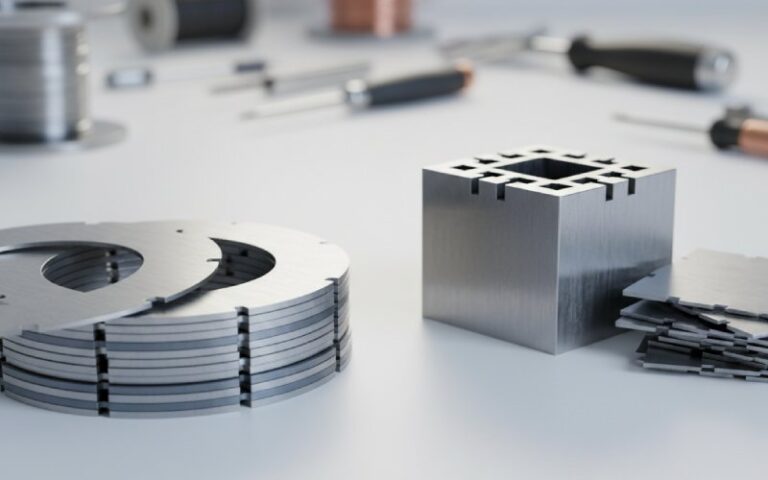
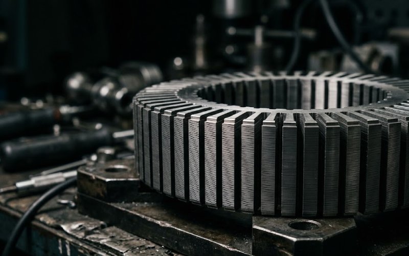
A humanoid robot’s shoulder has to hold up an arm while the wrist threads a needle. Same machine, wildly different motor problems. And at the bottom of both — literally, physically — sits a stack of stamped steel sheets thinner than a business card.
We build those stacks. The frameless PMSM and high-pole BLDC torque motors inside humanoid joint actuators are among the most demanding stator lamination stack applications we’ve shipped. Here’s what the production data actually shows about which lamination choices improve torque ripple, cogging torque, and smooth motion control — and which choices waste money.
Torque ripple in a joint motor shows up as jerky motion in the robot. The control loop can compensate for some of it, sure. But the electromagnetic source of that ripple — cogging torque, harmonic distortion, uneven flux distribution — gets baked in at the lamination level. Bad steel choice, sloppy tooth geometry, wrong stacking method, and the best FOC algorithm in the world won’t save you.
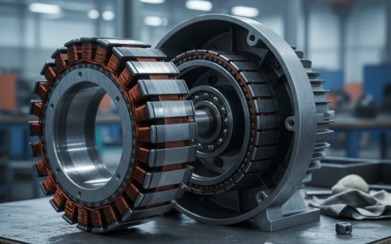
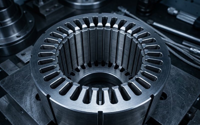
Joint motors for humanoid robots — the kind driving shoulder rotary actuators rated at 40–100 Nm peak, or knee joints pushing 100+ Nm — are almost always frameless PMSM or high-pole-count BLDC designs. No housing. No bearings of their own. The stator stack gets pressed directly into the robot’s structural joint housing. Any dimensional error in the stack becomes a concentricity error in the motor. Which becomes a torque ripple source.
The simulation doesn’t know your welds are shorting laminations together.
We’ve seen customers come in with beautiful FEA results, their model showing < 0.3% cogging at rated torque, and then lose 30–40% of that predicted performance because the stack wasn’t flat enough or the bonding method stressed the steel. The gap between simulation and reality, in joint motors, is almost always a lamination problem.
Not every joint in a humanoid robot needs the same lamination steel. Treating shoulder, elbow, and wrist motors identically is a common first-pass mistake that costs either money or performance — usually both. Current-generation humanoid platforms run 28–40+ actuators across the body, and the torque, speed, and precision requirements differ radically from joint to joint.
These carry the heaviest loads. Continuous torque requirements run from 40 Nm up past 200 Nm depending on the robot’s mass. The motor operates at relatively low speeds but must sustain high current densities for extended periods, so thermal performance matters.
For these high-load, moderate-frequency joints, we typically recommend 0.25–0.35 mm non-oriented electrical steel with silicon content around 2.5–3.0%. At the thin end (0.25–0.27 mm), the applicable standard is EN 10303 / IEC 60404-8-8 — the thin-gauge, medium-frequency specification — with grades like NO25-13 (0.25 mm, ≤ 13 W/kg @ 1.0 T/400 Hz) or NO27-15 (0.27 mm, ≤ 15 W/kg @ 1.0 T/400 Hz). For the 0.35 mm option, you move into the EN 10106 / IEC 60404-8-4 standard where grades like M270-35A (0.35 mm, ≤ 2.70 W/kg @ 1.5 T/50 Hz) apply.
Why the thickness split matters: a 10-pole-pair motor at 300 RPM runs at only ~50 Hz fundamental. At that frequency, the eddy current penalty difference between 0.25 mm and 0.35 mm is modest. Going below 0.20 mm for shoulder joints is rarely justified — you’re paying for thin gauge without capturing proportional loss reduction at these low electrical frequencies.
The permeability needs to be high because the motor design will push flux density to 1.6–1.7 T in the teeth at peak torque. Above that and you start saturating, which distorts the back-EMF waveform and feeds torque ripple straight into the output.
Mid-range torque (10–80 Nm), higher dynamic requirements. These joints accelerate fast and change direction often. The lamination priority shifts from raw thermal endurance toward low hysteresis loss and high permeability at moderate induction levels (1.0–1.4 T operating range).
We’ve had good results with 0.20 mm grades — specifically NO20-12 per EN 10303 (≤ 12 W/kg @ 1.0 T/400 Hz). The key insight from our production data: when you get the permeability right at the actual operating flux range (not the peak), the back-EMF linearity improves measurably. That feeds directly into cleaner current control. The servo loop gets smoother torque to work with.
Small stators. Fine teeth. Very tight slots. Torque requirements are modest (1–20 Nm) but the precision demand is extreme — these are the joints handling manipulation tasks, like the 22-DOF dexterous hands on current-generation platforms, where 0.1° position error matters.
Here we push into 0.10–0.15 mm ultra-thin NOES grades (NO10 or NO15 per EN 10303) or, for certain high-end programs, nickel-iron alloys in the 40–50% Ni family.
The Ni-Fe option gives phenomenal permeability ($\mur$ > 50,000 at low field) and almost zero cogging at the low flux densities these tiny motors operate at. The tradeoff: significantly higher material cost, lower $B{sat}$ (≈ 1.5 T for 48–50% Ni grades), and annealing requirements that depend on the specific alloy composition:
In a wrist motor that weighs 80 grams total, the cost premium on the steel is negligible relative to the robot’s overall BOM. The annealing, however, is not trivial — pick the grade that matches the magnetic performance you actually need, not the most exotic option available.
Worth noting: Ni-Fe laminations are sensitive to stamping stress. We prefer to laser-cut these and follow up with the appropriate anneal cycle. Progressive die stamping of Ni-Fe is possible — and for 0.15–0.20 mm thicknesses some programs do run it successfully — but the tooling has to be optimized for the material’s softness and ductility, and the post-stamp anneal becomes even more critical to recover properties lost to cold work.
| Parameter | Standard NOES 0.35 mm (EN 10106) | Thin NOES 0.20–0.27 mm (EN 10303) | Ultra-thin NOES 0.10–0.15 mm (EN 10303) | Co-Fe Alloy 0.10–0.20 mm | Ni-Fe 40–50% Ni, 0.10–0.20 mm |
|---|---|---|---|---|---|
| B_sat | 1.7–2.0 T | 1.7–2.0 T | 1.7–2.0 T | 2.3–2.4 T | 1.4–1.6 T |
| Core Loss @ 1.0 T / 400 Hz | 18–22 W/kg | 12–15 W/kg (0.25 mm); ≤ 12 W/kg (0.20 mm) | ≤ 13 W/kg (0.15 mm); ≤ 13 W/kg (0.10 mm) | Comparable to thin NOES at same gauge | Very low (< 5 W/kg typical at operating flux) |
| Permeability at 1.0 T | Good | Good–high | Good–high | High | Very high |
| Cogging Torque Potential | Standard | Improved | Further improved | Improved | Best |
| Stamping Difficulty | Easy; progressive die at 200–600 SPM | Moderate; burr control critical | Hard; burr-to-thickness ratio challenging | Hard; notch-sensitive, crack-prone | Hard; stress-sensitive, soft material |
| Post-Stamp Anneal | Optional SRA @ 750°C N₂ | Recommended | Recommended | Mandatory — vacuum or H₂ | Mandatory — temp/atmosphere depends on grade (see text above) |
| Relative Material Cost | 1× | 1.5–2× | 2–3× | 10–20× | 3–8× |
| Typical Joint Application | Shoulder, hip (where low-frequency operation makes 0.35 mm adequate) | Shoulder, hip, elbow, knee (the workhorse range for most joints) | Wrist, finger, precision end-effectors | Weight-critical leg joints on bipedal gait platforms | Wrist, finger, ultra-precision actuators |
| Stack Assembly | Interlock or weld | Bonding or interlock | Bonding (recommended) | Bonding (stress-free mandatory) | Bonding or clamp (no weld) |
Core loss values represent maximum guaranteed values per EN 10303:2015 and EN 10106:2015 where applicable, or verified ranges from our incoming coil Epstein testing for non-standard grades.
To clarify the overlap at 0.20 mm: this gauge sits right at the boundary. For joints where the fundamental electrical frequency stays below ~100 Hz (most shoulder/hip applications), 0.25 mm or even 0.35 mm captures most of the loss reduction and is easier to stamp. For elbow/knee joints with higher dynamic requirements and frequencies reaching 200–400 Hz, 0.20 mm is the sweet spot. We default to 0.20 mm when a motor design team hasn’t yet locked the gauge, because it gives the widest margin across the range of operating conditions typical in humanoid joints.
The way you hold laminations together isn’t just a structural decision. It’s an electromagnetic one. This is where we see the most “free performance” left on the table by teams that get the steel right but botch the stacking.
Laser or TIG welds along the outer diameter of the stack create localized short circuits between adjacent laminations. The heat-affected zone degrades the insulation coating and increases interlaminar conductivity. In our testing on 0.20 mm NOES stacks (NO20-12 grade), a four-seam laser weld added roughly 8–12% to measured core loss compared to the same stack bonded with adhesive.
That extra loss isn’t uniformly distributed. It concentrates near the weld lines. Depending on weld placement relative to slot positions, this creates asymmetric heating and introduces additional harmonic content into the flux distribution. We’ve measured it on an FFT of the cogging waveform — the 6th and 12th harmonic components increase noticeably on welded stacks versus bonded ones.
For industrial motors, nobody cares. For a joint motor where the spec says cogging < 0.5% of rated torque, it can be the difference between pass and fail.
Better than welding from an electromagnetic standpoint — no heat damage. But the interlock dimples create local deformations in the steel. Each dimple is a point of increased residual stress, which raises local hysteresis loss.
In small-diameter stators (anything under ~60 mm OD, which covers most wrist and elbow joints), there’s often not enough back-iron to place interlocks without affecting the magnetic circuit. We’ve seen cases where interlock placement in the yoke region of a 40 mm stator caused measurable flux density asymmetry in the airgap.
Self-bonding varnish (backlack) — classified as C-3 type per EN 10342 / IEC 60404-1-1 / ASTM A976 insulation coating standards — or post-stamp adhesive application produces stacks with:
Our adhesive layer thickness: 2–5 μm per interface. This keeps stacking factor above 97%. Thicker adhesive layers eat into active steel fraction and can reduce torque density by 2–3%.
Bonded stacks also run quieter. The adhesive between layers damps the high-frequency buzz that welded or interlocked stacks transmit into the robot’s structure. In a collaborative robot working near humans, audible hum from motor cores is a real UX problem. Bonding kills it.
Fractional-slot concentrated winding designs with high pole counts (16+ poles) are standard for joint torque motors. Common pairings like 12-slot/10-pole or 24-slot/22-pole inherently suppress low-order cogging harmonics. But the lamination still has to execute the geometry to spec.
A few things we’ve found matter more than the textbook suggests:
Tooth tip chamfering. We routinely add 0.2–0.4 mm chamfers to the tooth tips on stator laminations for robotics motors. In FEA, this reduces cogging by 15–25% on typical high-pole designs. But the improvement only materializes if the chamfer is consistent across all teeth to within ±0.03 mm. Inconsistent chamfers can actually increase cogging because they introduce geometric asymmetry that the fractional-slot design wasn’t meant to handle.
Burr height control. On 0.20 mm laminations, our production spec is ≤ 10 μm burr height. Every micron of burr is a potential interlaminar contact point that degrades insulation and creates eddy current paths. On thinner material (0.10–0.15 mm), the burr-to-thickness ratio gets aggressive fast.
For gauges below 0.15 mm, we typically switch to fiber laser cutting — primarily because it gives us tighter burr control and eliminates die wear as a variable. Progressive die stamping of 0.10 mm NOES is feasible (the material can handle slit, shear, and punch operations at room temperature), but maintaining consistent burr height below 10 μm across a full production run requires aggressive die maintenance schedules that most programs find impractical. Your mileage will vary depending on volumes and geometry complexity.
Slot opening width. Narrow openings reduce cogging but make winding harder and trap heat. The sweet spot for joint motors in the 40–80 mm stator OD range: typically 1.5–2.5 mm. The lamination tooling has to hold this dimension to ±0.02 mm across every slot, or the harmonic suppression from fractional-slot design gets partially negated.
Skewed lamination stacks reduce cogging torque by spreading the magnetic interaction over a larger angular range. It works. But it’s not free.
A continuous skew of one slot pitch virtually eliminates the fundamental cogging component. It also reduces average torque by 1–3% and complicates winding.
For high-pole joint motors with fractional-slot designs, most programs request half-slot or partial skew — enough to knock down residual cogging without sacrificing meaningful torque. We implement this as stepped skew using 2–4 sub-stacks rotated relative to each other.
Our standard capability: 2-step or 3-step skew with angular accuracy of ±0.3° per step. For tighter specs: 4-step configurations at ±0.15° — requires custom fixturing and adds cost.
One interaction that doesn’t get discussed enough: skew and stacking method. Welded stacks with stepped skew develop stress concentrations at each weld-step interface. Bonded stacks handle the slight angular offset cleanly because the adhesive accommodates it without hard contact points.
Amorphous and Nanocrystalline Materials: Why Not (Yet)
We get asked about amorphous metal ribbon for joint motors occasionally. The core loss numbers are spectacular — at ~0.025 mm thickness, loss drops by 70–90% versus NOES at comparable conditions. The practical problems are significant: – Stacking factor drops to 80–85%. You lose active magnetic material because the ribbon is ~25 μm thick with proportionally more coating/air per unit height. – Brittleness. Stamping complex stator geometries with fine teeth is borderline impossible at production scale. Laser cutting works but the heat-affected zone partially crystallizes the material, degrading properties. – B_sat ≈ 1.56 T — workable but lower than NOES. You need a larger core for the same torque, partially negating the loss advantage. For transformer cores and certain axial-flux topologies with simple wound shapes, amorphous makes sense. For the radial-flux frameless torque motors that dominate humanoid joint applications, it’s not practical today. Thin-gauge NOES with bonded stacking gets 80% of the theoretical benefit at 20% of the process difficulty.

Prototype lead time: 7–15 working days. Production: 6–8 weeks.
Stamping introduces plastic deformation at the cut edges and around any formed features. In Ni-Fe alloys, even moderate cold work increases coercivity and can drop permeability by 50–80% relative to the fully annealed state. The anneal recrystallizes the grain structure, eliminates dislocations, and restores the low-coercivity, high-permeability condition the alloy was designed for. The exact temperature and atmosphere depend on the grade: a 42% Ni alloy recovers well at 850–1000°C in a standard protective atmosphere, while a high-permeability 49% Ni grade needs 1100°C+ in dry hydrogen with controlled cooling to reach its rated permeability. Skimp on the anneal and you have expensive steel performing like cheap NOES.
A typical humanoid joint motor might have 10 pole pairs running at 0–500 RPM. That’s 0–83 Hz fundamental. Even at dynamic peaks of 1,500 RPM, you reach ~250 Hz. Compare that to an EV traction motor at 15,000 RPM with 4 pole pairs: 1,000 Hz fundamental. The lower frequency in joint motors means the eddy current penalty from thicker laminations is proportionally smaller. Going from 0.35 mm to 0.20 mm in a joint motor might save 15–20% on core loss. Going from 0.20 mm to 0.10 mm might save another 8–10% — but the stamping difficulty and cost increase are substantial. Match the gauge to the actual frequency, not to the thinnest thing available.
In our experience, consistency matters more than the exact chamfer dimension. A uniform 0.3 mm chamfer at ±0.03 mm across all teeth outperforms a 0.5 mm chamfer with ±0.08 mm variation. The variation introduces asymmetric reluctance that creates cogging harmonics the fractional-slot topology wasn’t designed to cancel. We hold chamfer tolerance tighter than most suppliers spec it.
No. Skewing suppresses the fundamental cogging component effectively, but the higher-order harmonics (6th, 12th, 18th) that come from geometric asymmetry — burrs, inconsistent slot openings, misaligned interlocks — are only partially attenuated by skew. You still need tight lamination tolerances. Skew is an additive measure, not a substitute for precision stamping.
Start from your FEA model’s flux density map and the operating frequency range. Define allowable core loss in W/kg at a representative operating point (e.g. 1.0 T/400 Hz per EN 10303 test conditions, or at whatever frequency matches your motor’s duty cycle). Specify the stack assembly method alongside the material — these are coupled decisions. If you bring us into the design loop before freezing material, thickness, and stack assembly method, we can usually identify 10–15% cost reduction opportunities without sacrificing electromagnetic performance. After the design freezes, we become a vendor executing a locked spec. Before it freezes, we’re an engineering partner.
If you’re developing joint motors for a humanoid robot program and need lamination stacks that actually hit the cogging and ripple specs your FEA promised, reach out to our engineering team. We’ll review your motor design, recommend a material and stacking approach, and quote prototype through production volumes.