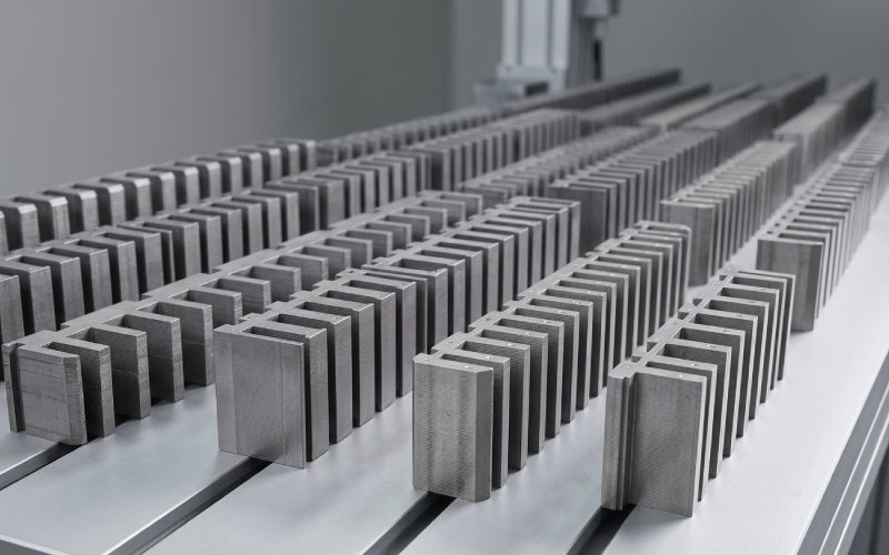
Let Sino's Lamination Stacks Empower Your Project!
To speed up your project, you can label Lamination Stacks with details such as tolerance, material, surface finish, whether or not oxidized insulation is required, quantity, and more.
More thrust usually pushes the stack harder. Lower cogging usually asks the stack to behave more gently. Tight tolerances are supposed to protect both, but they can also expose every weak point in the process. That is why, in our factory, thrust, cogging, and tolerance are never reviewed as three separate topics. They collapse into one stack decision very quickly.
For linear motor stator laminations, the real question is not just force output on paper. It is this: can the stack produce stable force, travel cleanly, and still stay manufacturable from prototype to volume.
A thicker stack can raise thrust. Sometimes. Not always.
What actually matters is how much usable magnetic steel ends up in the build, how clean the cut edge stays, how stable the lamination alignment remains after joining, and how much air-gap error the assembly adds later. A nominal stack height looks good on a drawing. The motor does not run on nominal stack height.
In many linear motor projects, thrust starts dropping for reasons that do not show up in the first quote:
That is why our custom lamination stacking service starts with a manufacturability review, not with tooling talk. Before tooling release, we check whether the force target is being carried by real stack quality or by assumptions that will disappear in the first build.
We typically lock down:
A force target that ignores those points tends to come back later as force ripple, heating, or travel inconsistency. Different symptom. Same origin.
For linear motor laminations, cogging is usually treated too late.
Teams often look at slotting first. That makes sense. But in linear motors, slot-related ripple is only part of the story. End behavior matters too. The stack does not live in an infinite magnetic circuit. It has entry, exit, discontinuity, and sometimes awkward force behavior near the ends. Clean average thrust can still come with poor travel quality.
In our factory, when a customer says, “the average force is fine, but motion is not,” we usually review these areas first:
Skew can help. It is not magic. If the basic geometry is already fighting the motor, skew just spreads the problem into a more expensive form.
A better path is usually this: reduce the low-order ripple sources first, then decide whether skew, segment shifting, or end-shape compensation is still worth the manufacturing cost.
That matters commercially, not just technically. When detent force is left for the control team to “fix later,” prototype loops get longer, tuning gets heavier, and production transfer becomes less clean. Buyers feel that as delay. Not as a magnetic issue. But it started as a magnetic issue.
This is where many precision motor lamination manufacturing programs split into two categories: the ones that scale, and the ones that keep passing samples but drift in production.
Single-sheet tolerance is rarely the real problem. Accumulated tolerance is.
In a linear motor lamination stack, small deviations start combining fast:
Not every error is large. That is the point. Several small errors, pointing the same way, are enough.
| Control item | Why it matters in linear motor laminations | What we focus on in production | What the customer gains |
|---|---|---|---|
| Stack height by count | Force consistency starts with actual build, not only nominal dimension | Sheet count discipline, compressed build check, lot consistency | More stable thrust from batch to batch |
| Burr height | Burr can disturb insulation and change local stack behavior | Tool wear tracking, edge inspection, deburring rule | Lower risk of hidden loss and variation |
| Slot pitch accuracy | Slot-related ripple gets worse when pitch accumulates | Progressive tooling accuracy, pitch verification | Cleaner travel and easier servo tuning |
| Flatness and straightness | Air-gap variation shows up directly in motion quality | Clamped inspection condition, fixture control | Less thrust fluctuation along travel |
| End-face geometry | End effect can dominate entry and exit behavior | End registration, squareness, profile repeatability | Better usable stroke quality |
| Joining zone | Joining changes both stiffness and magnetic behavior | Weld or bond placement, distortion control | Better balance between rigidity and force smoothness |
This is also why we prefer to discuss tolerance with the motor function in front of us. A drawing can say “within tolerance” and still build a stack that behaves badly in motion.
Joining is often pushed toward the end of the RFQ discussion. We do the opposite.
For custom lamination stacks, joining method changes more than handling strength. It can shift magnetic behavior, damage coating, pull the stack out of shape, or increase variability across the active length. A stack that is mechanically solid is not automatically a good motor stack.
In our projects, we do not choose joining by habit. We choose it by application:
Some stacks want a bonded route. Some are better with controlled weld placement. Some can use interlock features, but only if the magnetic tradeoff is acceptable. The wrong choice usually looks efficient on the shop floor first. The penalty arrives later.
Before production tooling starts, we review:
That saves time. More importantly, it prevents a false pass in early samples.
A good custom lamination stack program should not force the customer to choose between speed and control too early.
Our normal approach is straightforward:
We review force target, motion profile, available package space, expected air gap, and the areas where the stack is most likely to become tolerance-sensitive.
We look at slot geometry, end-face treatment, joining route, stack build logic, and whether the design can scale from prototype to volume without changing behavior too much.
For prototype motor laminations, the goal is not only to get parts quickly. It is to make sure the prototype teaches something useful for production.
Before tooling release, we define the control plan around pitch, burr, flatness, stack height, alignment, and joining stability.
Once the program moves into volume, the real job becomes consistency. Not one good batch. Repeated batches.
This is where buyers usually see the difference between a lamination supplier and a manufacturing partner. One ships parts. The other helps keep the motor stable over time.
A fast quote is useful. A usable quote is better.
For a better review of your linear motor stator laminations or custom lamination stacks, it helps to send:
If some of that is not fixed yet, that is still workable. Early-stage designs usually are not fully frozen.
Yes. We support prototype to production workflows for custom motor lamination projects. The main point is not only capacity. It is keeping the prototype route aligned with the future production route as early as possible.
Neither sits alone for long. Higher thrust can increase the sensitivity of the stack. Lower cogging can ask for geometry or process changes that affect cost, manufacturability, or available force. In practice, the stack has to balance all three: thrust, travel smoothness, and repeatability.
No. Force ripple is usually a stack-level issue, not just a single-sheet issue. Pitch accumulation, end geometry, joining distortion, burr, and air-gap consistency often matter more than one tight number on the lamination drawing.
Yes. Our engineering team can review linear motor laminations for manufacturability, tolerance sensitivity, joining options, and production risk before tooling release. That review is often where the biggest time savings happen.
Yes. Small-batch and prototype programs are common, especially when the motor design is still being validated. We can review the build path with that in mind instead of forcing a volume-only solution too early.
That depends on project requirements, but it usually includes dimensional checks, stack height confirmation, burr-related controls, flatness or straightness review, and other agreed inspection items tied to the stack function.
Usually not one dramatic defect. More often it is a stack of small issues: pitch drift, edge condition, joining disturbance, and air-gap sensitivity adding up until the motion stops looking clean.
If your project is already sensitive to thrust ripple, detent force, burr control, stack alignment, or joining-related distortion, it is better to review those points before tooling starts. Later is possible. Earlier is cheaper.
Need support with custom linear motor laminations?
Send us your drawings, target quantity, and key performance concerns. We can review the stack structure, identify the main manufacturing risks, and suggest a build path for prototype or production.