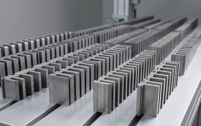
Let Sino's Lamination Stacks Empower Your Project!
To speed up your project, you can label Lamination Stacks with details such as tolerance, material, surface finish, whether or not oxidized insulation is required, quantity, and more.
A magnetic bridge is where you decide what you’re willing to be wrong about: stress margin, or electromagnetic cleanliness. Add steel and the rotor survives longer; keep it thin and the machine behaves better, until it doesn’t.
People talk about bridges like they’re only there to stop magnets from leaving the rotor. They are that. They’re also a deliberately saturated, geometry-defined shunt that rewires your leakage paths and shifts where flux density piles up. COMSOL’s own IPM stress/electromagnetic example says it plainly: saturation in the bridge region affects electromagnetic characteristics, so bridge thickness should be kept minimal to reduce losses, but those same narrow bridges see high centrifugal stress at speed.
That one sentence hides the real annoyance: “minimal” is not a number. It’s whatever still clears your mechanical constraints once you include the corners you actually manufacture, not the ones you sketched.
If you plot stress versus bridge thickness, you usually get the shape you’d expect from a structure that’s moving from “web-like” to “beam-like.” Early thickness buys a lot. After that, it’s diminishing returns.
One high-speed comparison study shows rotor stress dropping hard when bridge thickness goes from 1 mm to 2 mm (3961 MPa to 2385 MPa, about 39.8%), then dropping much less when going from 2.5 mm to 3.5 mm (1904 MPa to 1690 MPa, about 11.2%). That same “first millimeter matters” pattern shows up in another high-speed IPM optimization paper: increasing bridge thickness from 1 mm to 3 mm reduced maximum rotor stress while also pulling the no-load line back-EMF down (382.6 V to 348 V).
So yes, bridge thickness is a mechanical control knob. It’s also an EMF tax.
As bridges get thicker, leakage paths get easier. This is not subtle in simulation outputs; the no-load leakage flux factor in that same high-speed comparison rises from 1.12 to 1.56 as bridge thickness goes from 1 mm to 3.5 mm. That’s a tidy quantitative way to say: you paid for steel, then you paid again in leakage.
Then you add stiffeners or segment magnets to calm stress. Stress improves, leakage often gets worse. The same paper notes that splitting magnets and adding a stiffener increases leakage paths, with leakage factor rising roughly linearly with stiffener thickness, and it even reports a case where the leakage factor reaches 1.72.
And once leakage and saturation shape the air-gap flux waveform, you stop arguing about back-EMF magnitude and start arguing about its spectrum. That study shows higher back-EMF harmonic distortion for the IPM case than the SPM case (THD 3.20% vs 0.64%), with notable 11th and 13th components. Harmonics are where rotor core loss likes to hide.
Bridge decisions touch at least three “loss buckets,” even if you only track two in your dashboard.
The obvious bucket is rotor core loss. In the high-speed comparison, the authors directly tie the IPM rotor’s larger harmonic content (in part because of the small air gap and strong stator-current influence) to larger rotor core loss, and they show it turning into a rotor thermal limit problem (they report a maximum rotor temperature of 194 °C in their IPM case).
The second bucket is what your bridge does to local saturation and flux crowding. A Scientific Reports paper frames it as “high magnetic saturation at the flux isolation bridge” enriching air-gap flux density harmonics, which then increases torque ripple at low speed; their mitigation path is magnetic isolation holes that reduce bridge flux density by adding reluctance, aiming to avoid over-saturation and reduce hysteresis and eddy current loss.
The third bucket is the loss you create indirectly: you thicken bridges, you lose EMF (or power factor), you push for more current to hit torque, copper loss rises, and now you’re “fixing” a rotor stress problem by heating the stator. This isn’t a moral statement. It’s a bookkeeping statement.
One more non-intuitive detail from the high-speed optimization paper: rotor core loss can decrease as bridge thickness increases, even while EMF drops, because you changed how and where flux swings in the rotor steel; they report efficiency often rising then falling across bridge/stiffener thickness sweeps. So a thicker bridge can look “better” in one loss metric while quietly degrading the machine’s electromagnetic posture.
Once you stop pretending a bridge is a rectangle, the design space opens. Multi-bridge V-shaped rotors split magnets and insert middle bridges to distribute centrifugal forces, raising allowable speed, but the same paper states the contradiction directly: more bridges and more width improve mechanical strength while increasing flux leakage and reducing electromagnetic performance. Their results also highlight that central bridge thickness is an efficient mechanical lever, while some air-gap bridge parameter tweaks don’t buy much strength, implying you may choose air-gap bridge dimensions more aggressively for leakage reasons once the main stress path is handled elsewhere.
If you’re optimizing details like fillets and triangular bridge shapes, you’re usually chasing stress concentration, not average stress. A high-speed IPM optimization paper explicitly calls out fillet and triangular magnetic bridge schemes as part of the rotor-safety/electromagnetic conflict story.
A 2024 open-access paper proposes a rotor that eliminates bilateral bridges and keeps only a central bridge to maintain strength, explicitly targeting leakage and rotor iron loss; they combine high-silicon steel on the rotor surface (lower iron loss) with low-silicon steel internally (strength), and report reduced leakage, +7.5% torque, +0.18% efficiency, and −36.2% rotor iron loss versus the original motor.
This is the cleanest way to state the trade: if you shrink bridge width, you can win leakage and loss, but you must “buy back” mechanical integrity with topology (central load paths, segmentation strategy) and material choices.
| Bridge design move | What it usually buys mechanically | What it usually costs electromagnetically | What it often does to losses (directional) | Notes you’ll care about later |
|---|---|---|---|---|
| Increase air-gap bridge thickness | Big drop in peak stress early, then diminishing returns | Higher leakage factor; reduced back-EMF | Rotor core loss can go either way; waveform/harmonics often worsen | “Stress solved” can become “current increased,” which is just moving heat |
| Add stiffeners / segment magnets | Stress relief; different peak locations (often at stiffener root) | Extra leakage paths; leakage factor rises with stiffener thickness | Can reduce rotor stress but drive harmonic content that raises rotor core loss | The rotor might pass stress and fail temperature first |
| Multi-bridge (central + middle bridges) | Shares centrifugal load; higher allowable speed if geometry is right | More bridges/width tends to increase leakage | Depends on saturation map; leakage-driven harmonic shifts are common | Geometry alignment details (like middle-bridge direction) can matter more than count |
| Add isolation holes / notches near bridge | Not a strength play unless you compensate elsewhere | Reduces local saturation; can smooth flux distribution | Can reduce torque ripple and cut hysteresis/eddy components tied to saturation | Manufacturing and fatigue checks are not optional here |
| Reduce bilateral bridges, rely on central bridge + materials | Forces you to be deliberate about strength paths | Cuts overall bridge width, reducing leakage | Reported rotor iron loss reductions are possible in practice | Material brittleness/saturation tradeoffs show up fast (high-Si steel is not free) |
If you treat bridge sizing as “pick a thickness, then check losses,” you’ll iterate forever. The papers that look serious tend to treat it as coupled: stress, leakage factor, back-EMF spectrum, rotor core loss, temperature. One high-speed study even runs stress at 120% rated speed and elevated temperature to keep the margin honest, then ties the optimization objectives to efficiency and rotor core loss because rotor heating is often the limiter.
A practical stance is: decide what failure you refuse (yield at overspeed, rotor temperature ceiling, demag margin), then let the bridge be the smallest piece of steel that still makes those failures boring. Not optimal. Boring. The rest is managing the magnetic side effects with shape, segmentation, and where you allow saturation to happen, because saturation will happen anyway.