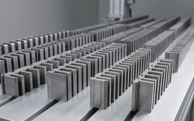
Let Sino's Lamination Stacks Empower Your Project!
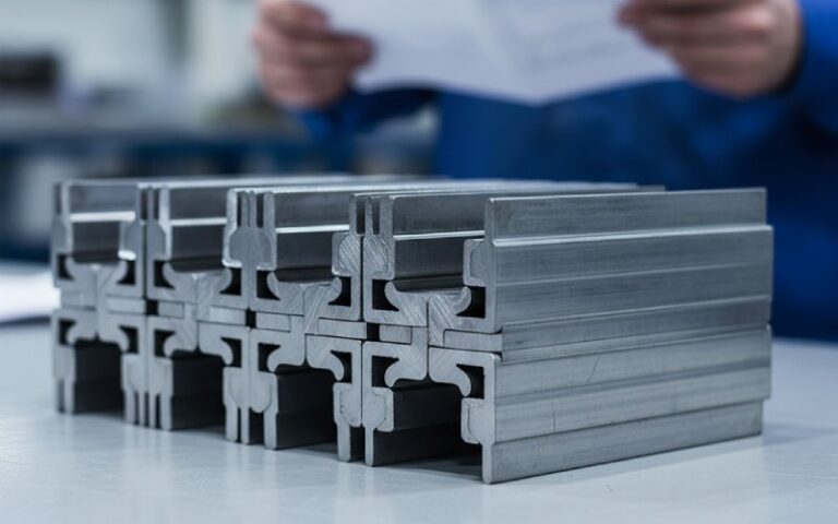
To speed up your project, you can label Lamination Stacks with details such as tolerance, material, surface finish, whether or not oxidized insulation is required, quantity, and more.
Short answer: yes, you can mix lamination thicknesses in a single stator or rotor, but almost every time it’s either a very deliberate design decision or a manufacturing compromise you accept with your eyes open. Standard motors stay with one thickness for a reason; mixing is for edge cases, cost fights, or repair situations where you are trading elegance for practicality.
Most of the public material on laminations stops at “thinner means lower core loss, thicker means better stiffness and cheaper stamping.” That part you already know. Typical modern machines sit in the 0.25–0.50 mm band for electrical steel laminations, often a bit thinner in stators and slightly thicker in rotors for strength. What people rarely talk about is what really happens if you start mixing those thicknesses in the same stack instead of just choosing one global value.
Let’s break that open.
When someone asks if they can mix thicknesses, they usually mean one of three things, even if they do not say it that way. One possibility is axial mixing: part of the stack length in one thickness and the rest in another, like 0.35 mm laminations in the central region and 0.50 mm near the ends. Another is radial mixing: laminations closer to the bore in one thickness, laminations toward the back iron or outer rim in another, using different stamping sets or compound parts. A third, more chaotic, case is repair or supply-driven mixing, where you substitute a batch of different-thickness laminations in the middle of an otherwise uniform stack because that is what you can get.
All three are technically possible. Stator and rotor cores are routinely built by stacking discrete laminations that can differ in geometry, coating and alloy; there is no physics rule that says every sheet must be identical. Modern stack assembly methods—interlocking, welding, bonding—already deal with collections of discrete plates. The real question is not “is it allowed?” but “what hidden costs do I pick up when I do it?”

You know the basics, so just a quick anchor. Eddy current loss in a lamination grows roughly with the square of thickness for the same material, peak flux, and frequency. That is why everyone keeps moving toward thinner sheets in high-speed and high-frequency machines, often down to 0.2–0.35 mm or even less in specialty designs. At the same time, thinner sheets mean more layers for the same stack height, more insulation interfaces, and a lower stacking factor, so the effective iron cross-section is slightly reduced.
On the mechanical side, thicker laminations and larger solid portions raise stiffness and make it easier to meet rotor burst margins and vibration limits, especially for very high speeds. Manufacturing sits in the background, quietly unhappy: thinner sheets slow down stamping, increase die wear, and demand more care in stacking and bonding.
Mixing thicknesses means you are playing with this trade-off locally instead of globally.
There are situations where mixing thicknesses is not just acceptable but useful.
One is high-speed rotors where the outer region needs extra mechanical robustness, while you still care about iron loss deeper in the core. A designer might consider thicker laminations or even a semi-solid outer ring for hoop strength, combined with thinner laminations nearer the magnet region or shaft to manage losses. Structural models already show how lamination thickness and solid-core diameter tie directly into rotor stiffness and stress.
Another is cost tuning for lower-speed motors. For grid-frequency induction motors at modest speeds, the difference in loss between 0.35 mm and 0.50 mm sheets is noticeable but not game-changing for all regions of the core. Studies show that changing from 0.50 mm to 0.35 mm laminations can raise efficiency by about one percentage point or so in small induction machines, mainly by reducing rotor core loss. If energy regulations force you to squeeze a bit more efficiency from a legacy frame, you might consider using thinner laminations only where the flux density and frequency product hurts most, keeping the rest at a cheaper thickness.
There is also the repair and retrofit angle. Sometimes you simply do not get the original lamination gauge anymore, or lead time is unacceptable. In that case, mixing thicknesses can be a controlled deviation that saves a project, provided you accept that you are now responsible for validating losses, no-load current, temperature rise, vibration and noise yourself.
Now the uncomfortable parts.
Electromagnetically, the stack no longer behaves as a uniform medium when you mix thicknesses. For a given outer geometry and nominal stack height, changing thickness in one region changes stacking factor and effective iron area locally. That shifts flux density, which in turn shifts both hysteresis and eddy current loss. If the mix is axial—say, 0.35 mm in the middle 60% of the stack and 0.50 mm near the end windings—you can get different local magnetization curves along the length. This can slightly distort the axial distribution of flux and loss, which might show up as temperature gradients or hot rings on a thermal image.
Radial mixing is trickier. If thinner laminations sit near the teeth where flux is already high and thicker ones near the yoke, you could lower tooth losses while keeping the back iron stiff. That sounds attractive. But the exact benefit depends on real operating frequency, waveform, and how much of the total magnetic path passes through each region. At higher electrical frequency or with rich harmonic content from inverters, the thinner part gains importance, and you may need a serious FEA study to know whether the total loss is actually improved compared to a uniform thickness design.
If mixing is unplanned and random—like dropping a batch of 0.50 mm laminations into the middle of a core designed for 0.35 mm—then flux tries to avoid the higher-loss region. You end up with subtle local saturation in the thinner layers just before and after the thick section, slight shifts in leakage paths, and sometimes ugly surprises in stray loss. None of this necessarily destroys the machine, but it makes analytical prediction less trustworthy and can break tight efficiency guarantees.
Mechanically, the stack is no longer a simple “spring” with uniform stiffness. Varying lamination thickness changes both radial and axial stiffness distribution. The outer rotor region is especially sensitive at high speeds; if the stiffness profile changes stepwise with radius or along the length, natural frequencies of the rotor can move closer to running speed or multiples of it. At that point, you start worrying about resonances you did not plan for.
Bonding and interlocking also depend on uniform geometry. Many assembly systems rely on repeating features, tabs or weld patterns that assume similar lamination thickness and surface conditions. If part of the stack is thicker, your clamping pressure distribution changes; interlock features may not engage in exactly the same way, and you risk local loosening or fretting between sheets. Poor bonding already shows up in practice as core vibration, mechanical noise and reduced life even with uniform laminations. Mixing thicknesses adds one more variable.
In stators, axial mixing can affect how the core interacts with the frame. The end zones already see different stress from clamping and shrink fits; change the stiffness near the ends and you may shift where the core “breathes” under electromagnetic forces, nudging noise and vibration patterns. Some designers will accept this if the motor is used in industrial environments where acoustic limits are forgiving. In automotive or appliance contexts with strict noise regulations, it is less appealing.
From the plant’s point of view, mixed thicknesses are almost always inconvenient.
Different thicknesses mean either different die sets or adjustable dies, separate runs, separate quality records, and usually different stacking processes. Modern punching lines are tuned for specific sheet gauges, and stamping speed and tool life both depend strongly on thickness. For example, industrial data shows that thinner stator laminations reduce the number of stacks produced per hour for a given motor height, at the same time stressing tools more. Switching gauge mid-stack breaks the smooth flow.
Stacking itself becomes more delicate. Burr height, flatness, residual stress, and coating thickness all scale with thickness and process parameters. If the burr pattern does not match, layers may not sit flat, and you get tiny air gaps or skewed slots. This degrades stacking factor and can form local eddy paths if burrs bridge insulation. The more variation you bring into the pile, the more the process depends on operator skill and strict inspection.
So, even if the electromagnetic idea looks clever on paper, the production engineer might push back simply because the line has to hit thousands of stacks per week and cannot indulge in delicate mixing patterns without cost.
Transformer core builders have been mixing lamination geometries for a long time: different step-lap joint pieces, different widths, different limb and yoke segments. Some patents describe using alternating lamination types to build up a target thickness and control magnetic performance. Most of the time, though, the thickness of the electrical steel gauge itself stays constant across the core. They change shape and overlap patterns, not the gauge, because mixing thicknesses complicates stacking factor, joint behavior and losses.
Motor and generator designers borrow the same lesson. Use geometry and segmentation creatively first. Treat mixed lamination thickness as a higher-complexity move that you justify only when you have a clear performance or cost reason and the analysis capacity to back it.
Here is a compact way to think about it.
| Scenario | Mix thicknesses? | Main reason to say “yes” | Main risk to manage |
|---|---|---|---|
| High-speed rotor with tight burst margin | Sometimes | Thicker outer laminations or solid rim for strength, thinner inner laminations for loss control | Complex stress and vibration modeling, assembly and weld sensitivity |
| Retrofitting existing low-speed motor to meet higher efficiency class | Maybe | Use thinner laminations only in highest-flux regions to reduce iron loss without fully redesigning tooling | Local hot spots, uncertain loss prediction, test burden |
| Prototype machine in R&D with full FEA and lab resources | Yes, if it answers a specific question | Freedom to experiment with axial or radial mixing and measure outcome | Not representative of final production process, limited replicability |
| Commodity industrial motor targeting cost and volume | Almost never | Hard to justify | Manufacturing complexity, QA overhead, more scrap risk |
| Emergency repair with mixed-stock laminations | Sometimes, as a controlled deviation | Getting a machine back online when exact replacement is unavailable | Performance drift vs nameplate, unknown lifetime, warranty implications |
This table is not a rulebook, but it mirrors how many experienced designers think once initial enthusiasm meets plant reality.
If you are going to mix, treat it as a real design variable, not an accident.
Start from the electromagnetic problem you are solving: maybe it is rotor iron loss at a specific harmonic, maybe stator tooth heating, maybe magnet temperature in a PM machine. Decide where along the flux path the thickness change will sit and what percentage of total core loss you are expecting to move. Use your normal FEA chain—2D cross-section first, then 3D or segmental—so that you see local flux density, local core losses, and any odd leakage patterns. Include the actual stacking factor difference between gauges instead of assuming a single constant.
Then overlay structural analysis. For rotors, include hoop stress, key speeds, and the effect of different lamination stiffness on mode shapes. For stators, look at how frame clamping and shrink fits distribute stress along the stack, especially if axial zones differ in thickness or material. Published work on rotor strength modeling shows how sensitive results can be to lamination geometry and solid core dimensions. This is where you avoid unwelcome resonances and speed limitations.
On the manufacturing side, involve the plant early. Ask how many different gauges and die sets are realistic. Check whether the stack assembly method—interlocking, welding, bonding—remains reliable across the thickness transition. Thin sheets can be much more sensitive to welding and bonding choices, with measured increases in loss when process parameters are not tuned for the specific gauge. That matters more when you mix.
Finally, validate in hardware with instrumentation that cares about the specific risks you introduced. That might mean extra core-loss tests, thermal mapping along the stack, or specific vibration measurements near the new mechanical transitions.

In stators, the case for mixing thicknesses is usually weaker. The stator core is clamped, not spinning, so mechanical demands are softer. You can often meet efficiency and temperature goals simply by choosing one appropriate thickness and a suitable steel grade, plus careful attention to slot geometry, tooth width and yoke depth. When designers want local tuning, they more often change lamination shape or use segmented stators than mix gauges.
Rotors are the opposite. For squirrel-cage induction rotors, there is a stronger argument: loss concentration and mechanical stress live together in the same space. Changing lamination thickness or even adding solid support regions gives you another lever, used in some high-speed or high-power-density designs. For permanent magnet rotors, the magnet arrangement and sleeve construction often dominate the mechanical game, but lamination thickness still plays into how the back iron saturates and how the rotor behaves at speed.
So, you might summarise it like this: mixing lamination thicknesses is more likely to be useful in rotors than stators, and more likely in special-purpose machines than catalog products.
Yes, you can, and people do, but mostly when they are chasing something very specific: a bit more efficiency without a new frame, higher safe speed, a particular thermal profile, or a one-off repair. The price you pay is extra complexity in analysis, manufacturing, and quality control. Standard practice of “one gauge per stack” exists because it is predictable, repeatable, and easy to manufacture at scale.
If you are thinking about mixing thicknesses in a stator or rotor, treat it the same way you would treat an exotic material or an unusual slot shape. Write down exactly what you expect to gain, model it with enough detail that the risks are visible, and involve the factory early enough that the reality check arrives before the tooling order, not after. Then, if the numbers still work, you are not just mixing thicknesses. You are doing intentional design.