Let Sino's Lamination Stacks Empower Your Project!
To speed up your project, you can label Lamination Stacks with details such as tolerance, material, surface finish, whether or not oxidized insulation is required, quantity, and more.
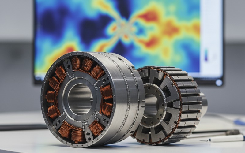
Modeling Welds and Interlocks in Stator and Rotor Electromagnetic Simulations
If you’ve ever had a motor model that looked perfect in FEA but missed test-bench efficiency, noise, or temperature by an annoying margin, there’s a good chance welds and interlocks were quietly sabotaging you. Those small, “manufacturing” details — laser weld seams, interlocking dowels, shrink-fit features — reshape the magnetic circuit and loss picture far more than their geometry suggests. Studies have shown that welding and joining processes alone can increase stator core losses by ~10–20% in industrial machines, and the combined impact of cutting, joining, and shrink-fitting can push losses up by 20–50% in some cases.
In this article we’ll:
Translate welding/interlocking manufacturing reality into EM model inputs you can actually use.
Compare several fidelity levels for including welds/interlocks in stator and rotor simulations.
Show how these details influence losses, torque ripple, and NVH — and when they truly matter.
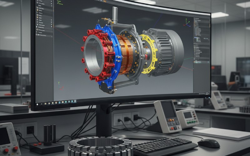
Give you a practical, tool-agnostic workflow you can adapt to Ansys Maxwell, JMAG, COMSOL, MagNet, etc.
Table of Contents
1. What welds and interlocks really do to your magnetic circuit
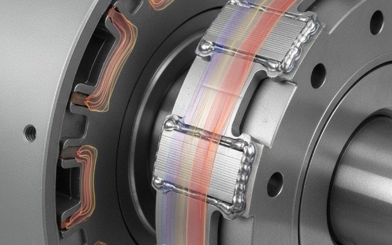
Under the hood, a laminated core wants to behave like a beautifully uniform magnetic path with clean lamination insulation and nice smooth B–H curves. Welds and interlocks deliberately break that ideal: they short laminations together locally, introduce plastic deformation and residual stress, and change how flux and eddy currents move through the steel.
At a physical level, welds and interlocks:
Connect laminations electrically, creating closed conductive loops that enable local eddy current “ring circuits.”
Introduce residual stress and plastic strain, degrading permeability and increasing hysteresis losses.
Disturb flux paths, especially near yokes and tooth roots, shifting local saturation and leakage.
Change stiffness and damping, which alters how electromagnetic forces translate into vibration and noise.
2. Quick tour of common joining methods and their EM implications
In real motors, you’ll typically see some combination of welding, interlocking, bonding, or mechanical compression:
Reality is messier. Papers on welded and interlocked cores show that:
Welding can increase stator core losses by around 10% in a 37 kW induction motor when modeled with measured welded ring-core data.
Interlocking processes can raise iron loss significantly; in some test geometries, the deterioration due to interlocking is comparable to or greater than punching itself.
For cut and joined cores, ignoring manufacturing degradation can underpredict losses by >50% in worst cases.
That leads to typical modeling pain points:
Loss underestimation (efficiency looks better in FEA than on the dynamometer).
Wrong hot-spot locations (poor thermal design because local loss peaks are missed).
Torque ripple & NVH mismatches (measured noise peaks with no obvious counterpart in simulation).
Confusing trade-offs (e.g., bonding vs welding) because your model treats all joining methods as electromagnetically identical.
4. The must-have inputs: talk to manufacturing early
You can only model what you actually know. Before you refine any EM model, spend a bit of time getting concrete data from manufacturing or suppliers.
A good “pre-simulation” conversation should at least clarify:
Joining technique for stator and rotor:
Weld type (laser, TIG, spot) and pattern (number, length, location).
Whether bonding / adhesive is used (and at what cure temperature).
Material & process data:
Steel grade and coating type (NOES vs GOES, insulation class).
Any available ring-core / Epstein data for processed material (cut + welded/interlocked).
Whether stress-relief annealing is applied after welding/interlocking.
Tolerance & pattern variability:
Typical positional tolerances on weld seams or interlocks.
Known “problem” variants (e.g., a certain interlock pattern that increased noise).
Put practically, ask:
“Where exactly are the welds / interlocks on the stack?”
“What does the process do to local magnetic properties — do you have test data?”
“Are there different joining options for the same stator/rotor we might compare?”
5. Modeling options: from “good enough” to high fidelity
In the literature, people generally fall into a few modeling “levels” when they deal with welds and interlocks. The trick is to choose the level that matches your design stage and risk.
Here’s a compact comparison you can use as a design cheat sheet:
Modeling level
What you do
What it captures
When it’s enough
Typical implementation tips
L0 – Ignore
No explicit weld/interlock modeling; single B–H & loss model.
Global torque & back-EMF shape.
Very early concept sizing, topological exploration.
Add generous design margins; never use for final loss prediction.
L1 – Effective material patches
Represent welded/interlocked zones as regions with modified B–H and loss coefficients in 2D/3D.
Extra local hysteresis & eddy losses; some flux disturbance.
Detailed loss estimation & efficiency maps for a given design.
Fit effective properties from ring-core / Epstein tests on welded or interlocked samples.
L2 – Explicit geometric features
Model weld seams or interlocking dowels as actual 3D volumes with realistic conductivity, plus locally degraded material.
Local eddy current loops, non-uniform flux, harmonic loss distribution.
Use 3D models with mesh refinement in dowel/weld regions; exploit symmetry; consider transient or multi-harmonic solutions.
L3 – Full multiphysics (EM + stress + NVH)
Couple mechanical FE (residual welding/interlocking stress, modal model) to EM model with stress-dependent B–H and magnetostriction.
Loss + deformation + modal shifts + radiated noise.
Final validation of flagship designs, EV traction or aero motors with strict NVH limits.
Map stress fields into EM mesh; use stress-dependent material models and pass EM forces back to structural NVH analysis.
When you’re trying to “beat the competition,” you generally want to get at least to L1 reliably and have L2 or L3 for your flagship motors.
6. Level 1 in practice: effective material zones for welds & interlocks
The core idea at L1 is simple: instead of redrawing every tiny weld or interlock, you paint “degraded material” onto the regions they influence and let FE handle the rest. This approach is common in modern research on cutting and joining effects, where people derive distance-dependent degradation models and apply them directly at element level.
A practical L1 workflow usually looks like this:
Step 1 – Get processed-material data
Measure ring cores made from actual stator laminations: unwelded vs welded; with vs without interlocking.
Extract B–H curves and core-loss coefficients for each case.
Step 2 – Build an “effective zone” model
Identify where welds/interlocks live (e.g., outer yoke seam, mid-yoke dowels, rotor pole joints).
Define zones (e.g., ±3–5 mm around each weld line or dowel) where material properties are modified.
Step 3 – Scale properties
Adjust permeability and core-loss coefficients in these zones based on your measurements (e.g., +10–30% local loss, slightly reduced µ).
Step 4 – Re-run EM sims
Evaluate total losses, local loss density, torque ripple, and flux distribution.
Compare with measurement if available (mock-up stator with blocked rotor, for example).
At L2, you stop pretending welds/interlocks are “just another material” and actually draw them. This is where you reproduce work like the 3D FE models of interlocking dowels (and equivalent 2D models derived from them) that explicitly show eddy current loops inside dowels and along the stack surface.
Key modeling moves at this level:
3D only where it matters
Use a 3D sector model with a few slots/poles and detailed dowels/weld seams; don’t jump straight to full 360°.
Preserve lamination thickness direction if you want realistic eddy current paths.
Separate materials for steel, weld metal, and dowels
Assign weld metal a high conductivity and appropriate µ (often closer to saturated or cast steel).
Treat dowels as a separate region that bridges laminations.
Resolve the time-dependence properly
Core losses from these features are frequency-sensitive; use time-stepping or multi-harmonic solutions.
For drive cycles, pre-compute frequency-dependent effective loss contributions and reuse them in system-level models.
Back-port results into 2D
From your expensive 3D study, derive an “equivalent loss and permeability map” that you can then implement as an L1-type material patch in faster 2D simulations.
8. Rotor-specific issues: welds, sleeves, and cages
Rotors tend to be modeled more crudely than stators, but welds and joints can be equally important there — sometimes more, because higher peripheral speeds and slot/pole combinations amplify local effects.
Common rotor-specific joining features include:
Welded or cast squirrel-cage bars and end rings.
Welded pole shoes or pole-to-yoke joints (for salient-pole machines).
Magnet-retaining sleeves or axial weld lines on permanent-magnet rotors.
Rivet / bolt joints on laminated pole assemblies.
When modeling rotor welds and joints, watch for:
Eddy current bridges between bars and laminations via welds, which impact rotor copper/iron loss split and cage heating.
Skew + weld interplay: welds near skewed slots can distort local flux paths and affect torque ripple.
Sleeve and shrink-fit stresses, which may degrade magnet and lamination properties and shift resonances when fully coupled.
9. From theory to clicks: a tool-agnostic workflow
Whatever EM solver you use, a good weld/interlock modeling flow tends to follow a similar backbone.
Think of it as “measure → reduce → model → validate”:
Measure / Collect
Gather ring-core / Epstein data for:
Base material.
Cut-only samples.
Cut + welded.
Cut + interlocked (with different patterns, if available).
If you can, measure core losses on partially assembled stator/rotor cores before winding (short-time test setups, toroidal excitations, etc.).
Reduce to models
Fit distance-from-feature degradation laws: e.g., a function µ(r), k_hyst(r), k_eddy(r) vs distance from weld line or dowel center.
Implement L1 patches (and optionally L2 geometry) in 2D/3D EM models of stator and rotor.
Run operating points covering:
Rated flux and frequency.
Over-fluxing and high-frequency PWM harmonics if relevant.
Validate and iterate
Compare simulated no-load, blocked-rotor, and load core-loss components against tests (or pre-assembly core measurements).
Tune degradation factors (within physically reasonable limits) until you consistently match core-loss and temperature measurements.
10. How weld/interlock modeling changes design decisions
Once welds and interlocks are in your EM model, they stop being “a necessary evil” and become design levers.
Instead of treating “welded vs bonded vs interlocked” as a purely mechanical or cost decision, you can look at it as an electromagnetic design variable:
With detailed modeling, you can:
Compare joining technologies quantitatively
Example: studies have shown bonded stator cores can reduce core losses by ~20–40% and significantly reduce acoustic noise compared to welded or interlocked cores in otherwise identical designs.
Optimize weld/interlock patterns
Minimize the number of interlocking dowels, or place them in regions of lower flux density to reduce extra loss while maintaining mechanical strength.
Tune yoke thickness and weld location together
Some segmented-stator designs use thin yokes that are more sensitive to misalignment and joint placement; FE models show this can increase cogging torque and alter resonance frequencies.
Assess rotor-side trade-offs
For example, deciding between welded and cast cages, or evaluating whether adding a retaining sleeve + local welds is worth the possible increase in rotor loss.
In practice, that can lead you to decisions such as:
Moving from interlocking to bonding for high-efficiency, low-noise EV traction machines.
Retaining interlocks but using fewer, optimally placed dowels while beefing up housing support.
Using welding only where absolutely necessary mechanically, and pushing for stress-relief annealing when EM penalties are high.
11. Closing the loop: validation, NVH, and future directions
Ultimately, weld and interlock modeling is less about drawing prettier CAD and more about making your virtual prototype behave like the real machine — including its imperfections.
A robust high-end workflow tends to look like this:
Paragraph-level reality check with hardware
Pre-assembly core loss measurement (ring cores, stator-only tests).
Full motor tests: no-load, blocked-rotor, load points; temperature rise and noise measurements.
EM + structural/NVH coupling
Use your weld/interlock-aware EM model to generate force harmonics.
Feed them into a structural model that also includes welded/interlocked joints and their stiffness/damping.
Compare simulated and measured vibration spectra; refine both weld/interlock stiffness and EM force modeling.
Data-driven shortcuts
As more projects accumulate, you can train internal surrogate models:
“Loss penalty vs weld pattern” for a given motor family.
“Noise penalty vs interlock density.”
Use those to quickly screen joining options before you commit to detailed FE.
Looking ahead, research is already moving toward:
Stress-coupled material models where B–H and losses depend directly on local mechanical fields, integrated into EM solvers.
Automated mesh/property assignment from process simulations (e.g., “import residual stress from welding FE into EM FE”).
Standardized degradation libraries for specific steel grades and joining processes, so you don’t reinvent the wheel on every program.
Cheney is a dedicated Senior Application Engineer at Sino, with a strong passion for precision manufacturing. He holds a background in Mechanical Engineering and possesses extensive hands-on manufacturing experience. At Sino, Cheney focuses on optimizing lamination stack manufacturing processes and applying innovative techniques to achieve high-quality lamination stack products.
New Product Brochure
Please enter your email address below and we will send you the latest brochure!
Let Sino's Lamination Stacks Empower Your Project!
To speed up your project, you can label Lamination Stacks with details such as tolerance, material, surface finish, whether or not oxidized insulation is required, quantity, and more.