Let Sino's Lamination Stacks Empower Your Project!
To speed up your project, you can label Lamination Stacks with details such as tolerance, material, surface finish, whether or not oxidized insulation is required, quantity, and more.
Motor core 101: stator vs rotor, slots, teeth, and back iron
If you’ve ever looked at a cutaway of a motor and thought “cool… but what exactly am I looking at?” — this guide is for you.
Most people talk about motors in terms of magnets, copper, and controllers. But quietly, the shape of the motor core — the stator, rotor, slots, teeth, and back iron — decides things like:
How much torque you actually get
How noisy or smooth it feels
How hot it runs and how long it survives
Under the paint and the plastic, it’s just steel, copper, and some air — arranged very deliberately.
What you’ll get from this guide
A clear, visual mental model of what “stator”, “rotor”, “slots”, “teeth”, and “back iron” really mean
An understanding of how these shapes steer torque, noise, efficiency, and cost
Enough vocabulary to have intelligent conversations with motor vendors or design engineers
Simple “knobs” you can think about when choosing or specifying a motor core
Table of Contents
1. Stator vs rotor: the basic picture
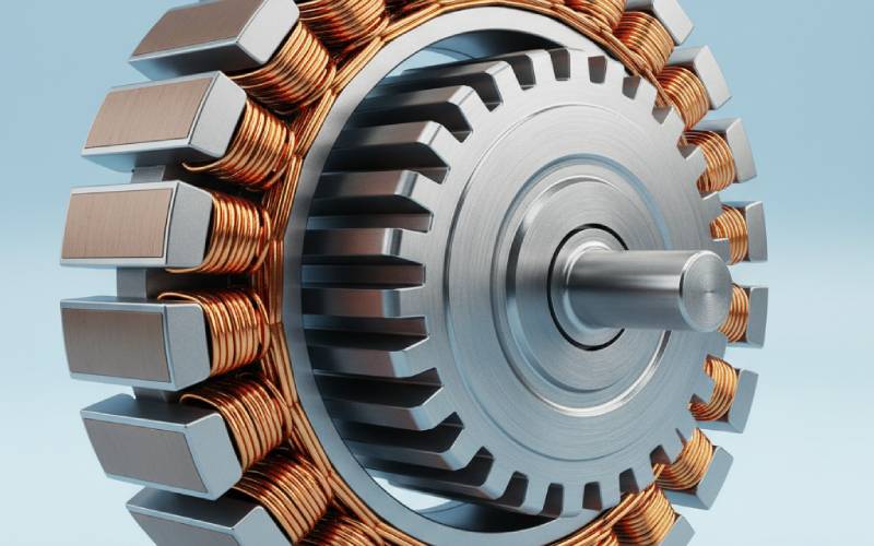
At its simplest, an electric motor is two rings of steel with a tiny gap between them:
The stator (stationary outer ring) holds the copper windings and creates a rotating magnetic field when energized.
The rotor (rotating inner ring) sits inside the stator and is dragged around by that field, converting electrical power into mechanical torque on the shaft.
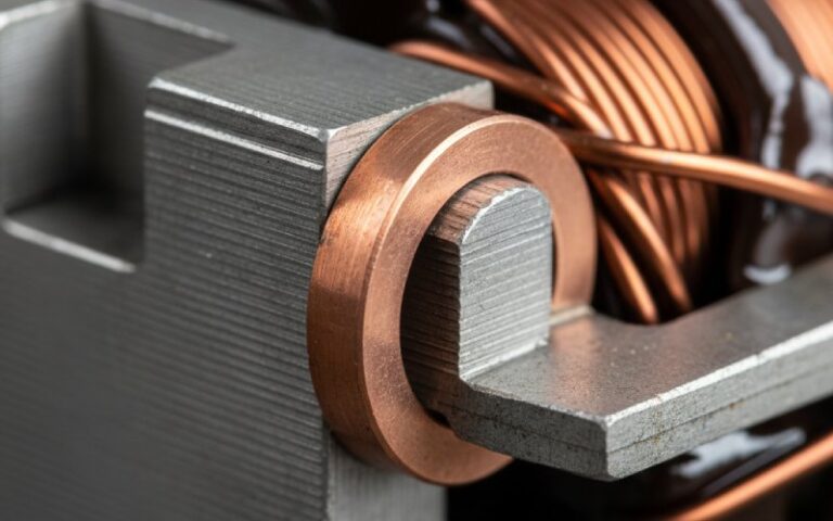
Both stator and rotor cores are built from thin laminations of electrical steel — typically silicon-alloyed steel — stacked like a very tight book. This lamination drastically cuts losses from eddy currents and hysteresis, and modern motor cores use lam thicknesses often in the 0.1–0.5 mm range.
The famous “air gap” between stator and rotor is small, but conceptually huge: making it a bit larger or smaller changes how hard the stator has to work to pull flux across it, and thus affects efficiency, torque, and sometimes acoustic noise.
Here’s an at-a-glance comparison you can keep in your head:
Aspect
Stator (Core + Teeth + Back Iron)
Rotor (Core + Slots/Teeth/Magnets)
Mechanical role
Fixed, bolted to housing; defines motor outer geometry
Rotates with shaft; defines spinning mass/inertia
Electrical role
Main place where windings live; creates rotating magnetic field
Responds to stator field; carries induced currents or permanent magnets
Magnetic role
Shapes flux in teeth, carries return flux in back iron (yoke)
Carries flux through rotor core and to magnets/slots
Typical core material
Laminated electrical steel
Laminated electrical steel
Design priorities
Copper space factor, cooling, tooth flux density, mounting, NVH
Inertia, flux capability, losses, mechanical strength at speed
Magnet demag, rotor bar fractures (induction), vibration, critical speed issues
Stator vs rotor: the key mental model
Stator = the “field sculptor”: it shapes where the magnetic field goes and how strong it is by geometry of teeth, slots, and back iron.
Rotor = the “follower” that turns field into motion: its geometry determines how faithfully it follows that field (torque ripple, slip, losses, demag margins).
You can think of stator design as mostly about creating a good field, and rotor design as about harvesting that field safely and efficiently.
Change stator geometry ⇒ you often change torque ripple, NVH, and efficiency. Change rotor geometry ⇒ you often change peak torque, magnet/rotor losses, and mechanical limits.
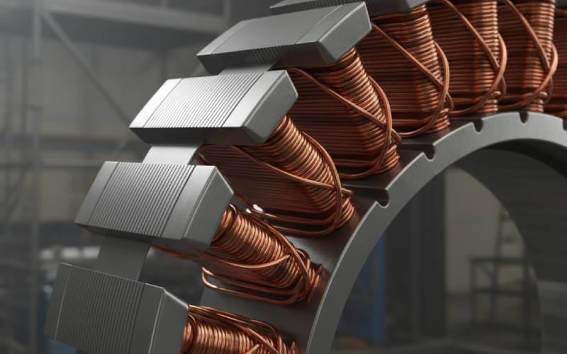
2. Slots and teeth: where copper meets steel
If you sliced a motor core like a donut, you’d see that neither stator nor rotor is a smooth ring. They’re “gear-shaped”, with repeated teeth and slots around the circumference.
Teeth are the radial protrusions of steel.
Slots are the gaps between teeth where the copper conductors live (stator) or where rotor bars/magnets sit (rotor).
Why bother with such a complicated shape?
Because teeth do two very important things:
They concentrate flux near the air gap, making the magnetic field stronger where it matters, boosting torque and back-EMF per unit copper.
They anchor the windings or magnets in a repeatable geometry, which is crucial for smooth operation and manufacturability.
However, the same teeth also create reluctance variation as the rotor turns — a magnetic “bumpy road” that becomes cogging torque and torque ripple if not managed.
Key stator slot & tooth design “knobs”
Number of slots (Q)
More slots: smoother torque, lower cogging, better waveform shaping, but more complex winding & higher manufacturing cost.
Fewer slots: simpler, often cheaper, but can mean higher torque ripple and acoustic noise.
Slot/pole combination (e.g., 12s/10p, 9s/6p)
Determines slots per pole per phase (q), which strongly affects winding factor, cogging torque, and harmonic content of the air-gap field.
Slot shape (open, semi-closed, fully closed)
Open slots: easier to wind, higher leakage, potentially higher cogging; tend to be cheaper.
Semi-closed: good compromise for many industrial motors.
Closed or near-closed: low leakage and potentially low noise, but harder to wind and cool.
Tooth width & height
Wider teeth → more flux capacity, less chance of saturation, but less space for copper in slots.
Taller teeth → can help layout, but increase path length for flux and may hurt mechanical stiffness.
Slot liner & insulation strategy
Directly affects copper fill factor, thermal path, and partial discharge margins at higher voltages.
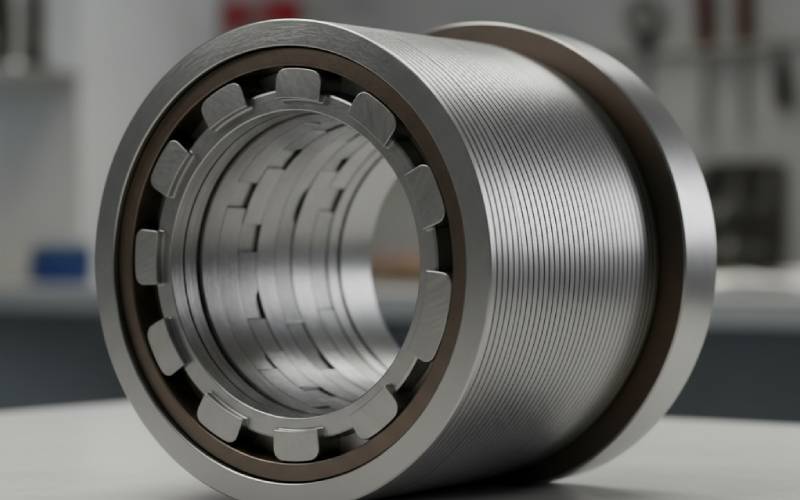
3. Rotor slots and teeth: subtle but powerful
The rotor’s geometry is just as influential — even though it’s spinning too fast for you to stare at.
In induction motors, the rotor slots hold conductive bars (forming a “squirrel cage”) that carry induced currents. In permanent-magnet machines (PMSM/BLDC), they often define where magnets sit, or where flux bridges live in an interior permanent magnet (IPM) design.
Rotor slots and teeth affect:
How flux crosses the air gap and spreads in the rotor core
How starting torque vs efficiency trade off (for induction machines)
How exposed the magnets are to harmonic fields and demagnetizing pulses (for PM machines)
Rotor laminations, like stator laminations, are stacked thin electrical steel with carefully chosen grades and thickness to minimize core loss while surviving mechanical stress at speed.
Important rotor-side design levers
Slot count vs stator slot count
Certain stator/rotor slot combinations lead to undesirable “slot harmonics” and torque ripple or noise. Smart choices avoid common resonance patterns.
Rotor slot shape (deep, skewed, semi-closed)
Deep, skewed slots in induction motors improve starting torque and significantly reduce noise and torque ripple, at the cost of some efficiency.
Magnet placement (surface vs interior)
Surface-mounted magnets: simpler, high torque density but typically higher cogging and risk of mechanical stress at speed.
Interior magnets: better field shaping, wide constant-power speed range, mechanical containment at high RPM, but more complex lam geometry.
Flux barriers and bridges (IPM motors)
Carefully shaped voids in the rotor core steer flux so that torque comes mostly from reluctance and magnet torque together. Tiny changes in these shapes can make big differences in performance and noise.
Mechanical margin at speed
Hole patterns, keyways, magnet pockets, and skew all reduce effective cross-section for strength, so rotor design is always a balance between magnetic performance and burst speed margin.
4. Back iron (yoke): the quiet backbone of the magnetic circuit
“Back iron” or yoke is the ring of steel behind the teeth, away from the air gap. It’s the return path for magnetic flux:
Field leaves a stator tooth, crosses the air gap, passes through the rotor,
Returns through the rotor back iron,
Crosses the air gap again at another tooth,
Then flows through the stator back iron/yoke to complete the loop.
Good back iron design is about not getting in the way of that flux:
Too thin → flux density gets high, steel saturates, torque stops scaling with current, losses skyrocket.
Too thick → you’re hauling around extra steel and cost with little gain.
Because stator back iron often doubles as a mechanical frame and mounting surface, its geometry has to juggle magnetic, mechanical, and thermal requirements at the same time.
Back iron: what you should pay attention to
Flux density targets
Many designs aim to keep back-iron flux density in a band that balances torque capability vs loss (often somewhere in the ~1.2–1.7 T range depending on steel grade and application).
Local “pinch points” under high-loaded teeth
High-torque regions (e.g., concentrated windings) can create local saturation just under certain teeth while the rest of the yoke is fine. FEA tends to reveal this quickly.
Split housings and assembly features
Bolt holes, ribs, cutouts for cables, and cooling passages all eat into back-iron cross-section; they must be placed so they don’t choke the main flux loop.
Rotor back iron under magnets
In PM machines, rotor back iron must be thick enough that magnets “see” a low-reluctance path; too thin and the magnets saturate the rotor, wasting magnet potential and risking demagnetization under fault conditions.
5. One electrical cycle: how stator, rotor, slots, teeth, and back iron work together
Let’s walk through a very simplified mental animation of a 3-phase PM motor during one electrical cycle:
Picture a single stator tooth. Around it, in the slot on either side, is copper belonging to some phase. When that phase is energized:
Current flows in the coils, turning that tooth into a strong electromagnet.
Flux leaves the tooth face, crosses the air gap, enters a rotor magnet or tooth, spreads into the rotor core/back iron, and returns via other teeth and the stator back iron.
Now imagine the three phases firing in sequence. The “which tooth is energized” pattern rotates around the stator:
To the rotor magnets, this looks like a rotating magnetic field.
The rotor tries to follow this rotating field; in PM machines it locks in with small slip, in induction machines it chases it with some slip.
The details — how strong the torque is, how smooth the rotation feels, and how hot the core runs — are all set by:
How much area the tooth face has before it saturates
How the slot shape and slot/pole combination shape harmonics in the field
How thick the back iron is and how well it carries the return flux
Sequence of events over a cycle (simplified)
Phase A’s teeth are strongly excited → flux peaks through those teeth and corresponding rotor regions.
As the currents rotate (A→B→C), neighboring teeth take over, and the “hotspot” of flux marches around the stator circumference.
The rotor’s magnets or cage conductors see a rotating field vector and develop torque trying to align with that vector.
In each instant, some teeth and yoke regions are close to saturation, others are lightly loaded — the pattern depends heavily on slots, teeth, and back-iron geometry.
Over many cycles, losses in teeth and back iron (hysteresis, eddy current) turn into heat; lamination thickness and steel grade are chosen to minimize these while still being manufacturable.
6. How these geometry choices show up in the real world
All this might feel abstract until you connect it to what you actually experience from a motor:
Torque density: how much torque you get per unit size/weight
NVH (noise, vibration, harshness): how “whiny” or “coggy” it feels
Efficiency & range (for EVs, robotics, batteries)
Thermal headroom and reliability
Manufacturers quietly tweak slots, teeth, and back iron to hit their preferred trade-offs.
For example:
More, narrower teeth (higher slot count) with a good slot/pole combination can dramatically reduce cogging torque and acoustic noise.
Using higher-grade lamination steel and thinner lam stacks can cut core losses, especially at high frequency (high electrical speed), improving efficiency.
Carefully optimized rotor slot geometry or magnet placement can give a flatter efficiency vs speed curve or more usable constant-power region.
If you want… then your core geometry should lean toward…
Rotor with carefully controlled mass and strong containment (IPM or buried magnets; small “holes” in rotor back iron).
Stator slots shaped to keep losses and stress manageable at high electrical frequency.
Low cost and easy manufacturing
Moderate slot counts, simple slot shapes, good but not exotic lamination grades.
Stator and rotor designed for stamping with minimal scrap and easy stacking.
7. Questions to ask a motor supplier (that show you really understand cores)
You don’t need to be the person running FEA to sound extremely competent in a design review. A few well-targeted questions about stator, rotor, slots, and back iron will immediately signal that you’re thinking beyond just “kW and RPM”.
Practical, geometry-centric questions
“What slot/pole combination are you using, and how did you choose it with respect to cogging torque and harmonics?”
“What lamination grade and thickness do you use for the stator and rotor, and how does that impact core losses at our operating speed?”
“What are your target flux densities in the stator teeth and back iron at rated torque? Where are you closest to saturation?”
“Is the rotor skewed? If so, by how many slot pitches, and what trade-off did you make between torque and NVH?”
“How do you manage thermal paths from teeth and back iron into the housing — are there known hot spots in the core under peak load?”
“What kind of FEA validation have you done for local saturation in the yoke near mounting features or cooling channels?”
“If we asked for +10% peak torque, where would your design bottleneck first: teeth, slots, back iron, or rotor?”
8. Wrapping it up
If you strip an electric motor down to its essence, you get:
Two rings of laminated steel
A pattern of slots and teeth that guides copper and flux
A back iron structure that quietly closes the magnetic loop
But the way those rings and teeth are arranged is where the magic — and the competitive edge — really lives.
Stator: shapes the rotating field and carries most of the copper.
Rotor: turns that field into mechanical work and holds magnets or bars.
Slots & teeth: decide how cleanly torque is produced and how noisy the motor is.
Back iron: decides how comfortably the flux flows and how close you’re running to the edge of saturation.
Cheney is a dedicated Senior Application Engineer at Sino, with a strong passion for precision manufacturing. He holds a background in Mechanical Engineering and possesses extensive hands-on manufacturing experience. At Sino, Cheney focuses on optimizing lamination stack manufacturing processes and applying innovative techniques to achieve high-quality lamination stack products.
New Product Brochure
Please enter your email address below and we will send you the latest brochure!
Let Sino's Lamination Stacks Empower Your Project!
To speed up your project, you can label Lamination Stacks with details such as tolerance, material, surface finish, whether or not oxidized insulation is required, quantity, and more.