Let Sino's Lamination Stacks Empower Your Project!
To speed up your project, you can label Lamination Stacks with details such as tolerance, material, surface finish, whether or not oxidized insulation is required, quantity, and more.
You already know the physics. This glossary just pins down the words that actually drive loss numbers, noise complaints, quotes from steel vendors, and arguments in design reviews, across both motor cores and transformer laminations.
Most of the soft-magnetic drama in modern machines doesn’t come from Maxwell’s equations. It comes from how laminations are cut, insulated, stacked, clamped, and described on drawings and in steel datasheets. Manufacturing steps like punching, stacking, and housing can easily shift hysteresis and eddy-current losses away from the “catalog” values by adding plastic deformation and residual stress to the edges of laminations. In transformers and motors, that translates straight into extra watts of core loss, hotter spots, and sometimes failed efficiency guarantees.
So the terms below are written for someone who can already read a B–H curve, but wants shared language with purchasing, core shops, and FEA specialists.
Electrical steel is the default material for laminated cores: a silicon-alloyed, low-carbon steel optimized for low loss and decent permeability at power frequencies and beyond. Its losses are often decomposed into quasi-static (hysteresis-dominated), parasitic (eddy-current-like), and anomalous or excess components in modern models. You rarely see those three words in a quote, but that’s what sits behind “W/kg @ 1.5 T, 50 Hz”.
Grain-oriented electrical steel (GO, CRGO) is rolled so that the easy magnetization axis lines up with the rolling direction. It is designed for flux that mostly flows along that direction, which is exactly what happens in classic transformer limbs and yokes. Use this when your flux paths are tidy and mostly one-dimensional, not in a heavily toothed stator where directions change all around the air gap.
Non-oriented electrical steel (NO, CRNO/CRNGO) has roughly isotropic magnetic properties in the sheet plane. Motors and rotating machines rely heavily on this because flux is circulating through teeth, back iron, and bridges in many directions. NO grades typically have higher loss than GO at 50/60 Hz in their “favorite” direction, but they don’t punish you when flux swings off-axis.
When someone says simply “M235-35A” or similar, you are looking at a thickness (around 0.35 mm) and a loss class; the electrical steel vendor’s datasheet tells you how optimistic those numbers are under Epstein test conditions compared with your punched, clamped reality.
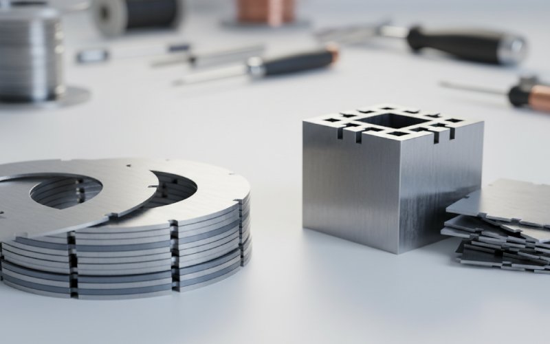
A lamination is one thin sheet of electrical steel, coated with an insulating layer (“coreplate”) and stacked to form the magnetic circuit. Laminating limits eddy-current paths and lets you trade thickness against loss: thinner lamination → smaller eddy-current loops → lower eddy-current loss at a given frequency, but more cost and lower packing efficiency.
Lamination thickness / gauge is usually in the 0.18–0.50 mm range for power applications. Thin gauges (0.18–0.23 mm) are used for high-frequency, low-loss designs or amorphous alloys; thicker gauges (~0.35–0.50 mm) are cheaper and acceptable at low frequencies where hysteresis dominates. The correct thickness is not just about loss; it also imposes constraints on punching and handling.
Coreplate / interlaminar insulation is the thin coating applied on each lamination to keep them electrically separated. It carries several jobs at once: limiting interlaminar currents, surviving punching, surviving annealing (if any), resisting moisture and corrosion, and not eating up too much stacking factor. Degraded interlaminar insulation leads directly to local shorted turns through the stack, higher local loss, and can be detected by specialized flux-injection and surge tests on stacked cores.
Stacking factor (also called lamination factor or space factor) is the ratio of the effective iron length to the measured stack length. In other words, how much of your stack height is steel vs. coatings and air pockets. Typical numbers for silicon steel cores are around 0.95–0.97; amorphous strip cores might sit closer to ~0.8 because of rough surfaces and coatings.
Designers use stacking factor in two ways. First, they correct the net magnetic cross-section used in FEA and hand calcs (B = Φ / A_eff, and A_eff includes stacking factor). Second, they feed it back to vendors in tolerance discussions: if you specify an aggressive stacking factor but allow burrs, waviness, and thick coatings, something will not match.
Magnetic aging is the long-term drift of core loss and permeability due to stress relaxation, oxidation, or improper annealing. It often appears as a gradual increase in W/kg over years of operation or after repeated thermal cycling. You rarely see it called out explicitly in machine specs, but any steel datasheet that mentions “guaranteed loss after aging” is quietly talking about it.
The table below compresses some of the common lamination-related terms into the way they actually show up in conversations. Typical numeric ranges are indicative; vendors and standards fill in the exact values.
| Term | Typical range / options | More common in… | What people actually argue about |
|---|---|---|---|
| Lamination thickness | 0.18–0.50 mm (Si steel), thinner for amorphous | Both | Loss vs cost vs punching difficulty |
| Stacking factor | ~0.80 (amorphous) to ~0.97 (Si steel) | Both | Whether the assumed value in FEA matches test results |
| Electrical steel type | GO, NO, amorphous, high-silicon variants | GO: transformers; NO: motors | Price vs loss vs availability vs noise |
| Coreplate / insulation class | Vendor-specific coating types, different thermal and dielectric ratings | Both | Whether the coating survives process and clamping |
| Joint type (butt / miter / step-lap) | Butt, simple miter, step-lap mitered joints | Transformers | No-load loss, acoustic noise, and build complexity |
| Slot fill factor | Roughly 0.4–0.6 in many practical motor stators | Motors | Manufacturability vs copper loss vs thermal performance |
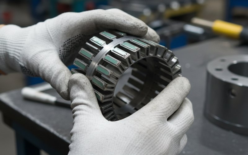
In motors, the stator core is a ring of laminations carrying teeth and slots. The rotor core is another laminated structure that may carry permanent magnets, squirrel-cage bars, or saliency. The lamination vocabulary mostly bites at the stator, where tooth geometry, slot opening, bridges, and back iron thickness are etched into the sheet.
Teeth are the protrusions that carry the windings around their sides. Their width, taper, and tip geometry decide flux density in the tooth and the saturation margin at overload. Slots are the voids that hold the conductors; their shape sets slot leakage, slot harmonics, and mechanical constraints for winding insertion. Slot geometry also controls local stress concentrations from punching; that matters for loss modeling near edges.
The back iron (or stator yoke) is the ring region outside the teeth that closes the magnetic circuit. Its thickness is sized from flux requirements and stacking factor, using standard design relations; in many textbooks and design reports, you’ll see algebra where lamination stacking factor explicitly scales back-iron width.
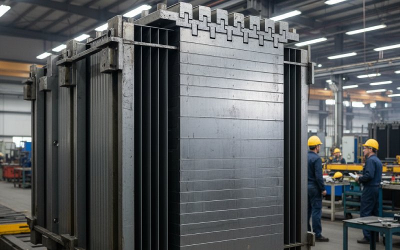
In core-type transformers, limbs (or legs) are the vertical columns of laminations that carry primary and secondary windings. The yokes are the horizontal sections that link limbs together and provide the return path. Together, they form a closed magnetic circuit.
The core window is the opening bounded by limbs and yokes. It houses windings, insulation, cooling ducts, and clamping structures. Its height, width, and clearances feed into the window space factor and dictate how ambitious you can be with copper cross-section and insulation levels.
An interesting shared term across machines is air gap. In motors, air gap is a designed feature between stator and rotor; in transformer cores, “air gaps” are more often imperfections: joint gaps, misalignment, or deliberate small gaps in special designs like gapped inductors. In both cases, the lamination vocabulary shows up when you talk about how accurately the stack is machined or ground.
Core loss or iron loss is the power dissipated inside the magnetic material when it is subject to a time-varying flux. It’s usually reported as specific loss in W/kg at a given induction B (e.g., 1.0–1.7 T) and frequency (50/60 Hz or higher). For electrical steels, modern models split this into hysteresis, classical eddy-current, and excess components, even when the catalog only prints one W/kg number.
On a steel datasheet, you might see several test points (for example at 1.5 T, 50 Hz and 1.7 T, 50 Hz). Those points hide process assumptions: clean Epstein strips, no punching damage, and ideal stacking. Once laminations are punched, bent, and clamped, measured losses on assembled cores usually increase due to mechanical stress and damaged edges.
Hysteresis loss is associated with the area of the B–H hysteresis loop. Each cycle, energy is lost to domain wall motion and irreversible magnetization. First-order design changes like material grade, flux density, and annealing state strongly influence it. In transformers, running closer to saturation or using a steel grade with higher coercivity shows up here.
Eddy-current loss arises from circulating currents induced within each lamination; it scales strongly with lamination thickness and operating frequency. Thinner laminations and better interlaminar insulation restrain these currents. Improper stacking (gaps, burrs, shorted surfaces) can bypass the benefit.
Excess loss (sometimes “anomalous” loss) accounts for additional frequency-dependent loss beyond the simple eddy-current model, linked to microstructural details and domain wall bowing. Modern materials and models include this term, especially at higher frequencies and complex waveforms.
Design teams may not always name “excess loss” explicitly, but when FEA results don’t match measured loss at higher harmonic content, this is the silent culprit.
Flux density B in the core is computed from your net flux and effective area; stacking factor adjusts that area. You already know the B–H curve, but in lamination language you often hear “knee point” or “knee flux density” of the steel grade. That’s the point on the magnetization curve where incremental permeability starts to drop fast. Operating too close to this knee drives up hysteresis loss and distorts waveforms.
Saturation is the practical upper limit where increasing magnetizing force H adds little B but adds a lot of loss and heating. In EI transformers and small motors, designers often keep nominal operation comfortably below the knee, but transients and harmonics nudge local regions higher.
Magnetostriction is the strain induced in the material when magnetized. It couples magnetic design to vibration and audible noise. Step-lap joints in transformer cores, for example, are used not only to cut no-load loss but also to reduce magnetostrictive strain concentration at joints, lowering hum.
Transformer laminations can be assembled in several joint styles:
A butt-lap joint cuts laminations square and butts them against each other. This is simple to manufacture but leaves relatively large effective gaps and higher local flux crowding.
A mitered joint cuts laminations at angles (often 45°) so that flux crosses the joint more gradually and stays closer to the rolling direction of grain-oriented steel. That improves loss and reduces local saturation compared with butt joints.
A step-lap joint goes one step further. Laminations are overlapped in small steps (often 3–5 layers) at the joint, so flux sees a staged transition rather than one sharp interface. This arrangement significantly reduces no-load core loss, improves flux distribution through the joint, and lowers magnetostriction-driven vibration and noise.
The glossary piece hidden behind these words is about what you negotiate with core suppliers: more complex joints mean more cutting passes, more stacking work, and stricter alignment requirements, but they buy loss reduction and quieter operation.
When laminations are stacked, they are often grouped into packets: small sub-stacks treated as units in a larger step-lap or circular build. Packet design tries to keep each step a convenient multiple of lamination count so that assembly stays repeatable.
Burrs are the raised edges left by punching or shearing. Even small burrs matter twice. Mechanically, they affect how tightly laminations lie together and thus the stacking factor. Magnetically, they offer unwanted conductive bridges between laminations, which increase interlaminar currents and distort local fields.
Skewing in motors is the slight twist of the stator or rotor lamination stack along the axial direction. It is used to reduce cogging torque and torque ripple at the price of manufacturing complexity, altered slot leakage, and sometimes higher copper length. In lamination terms, skewing also complicates punching patterns and stacking jigs.
Stacking pressure, clamping plates, and tie bolts all feed into the final effective stacking factor and the stress state of the steel. Too loose and you see vibration and rattling, plus inconsistent losses. Too tight and you induce extra stress, which raises hysteresis loss near the joints and edges.
Slot fill factor is the ratio of the total conductor cross-sectional area (usually copper) to the physical cross-sectional area of the stator slot. In many industrial machines, real-world values in the range of about 0.4–0.6 are common, depending on conductor shape, insulation thickness, and winding method.
Designers also talk about copper fill factor, which sometimes refers specifically to the ratio of bare metal area to slot area (ignoring insulation), sometimes to total conductor plus insulation. The exact definition is messy in practice, so in design reviews it helps to clarify which one your FEA or spreadsheet is using.
Slot fill factor bridges electromagnetic and manufacturability language. A high target factor can look great in thermal and copper loss models but may be unrealistic for automatic insertion or hairpin bending tolerances. So it’s a number you negotiate between simulation, winding engineering, and the core stack dimensions.
In transformers, window space factor is the ratio of area occupied by conductors to the total window area that windings can occupy. It needs to leave room not just for copper, but also for insulation, cooling ducts, interleaving schemes, and clearances to meet dielectric test levels.
The window space factor interacts with lamination design because changing limb width, yoke height, or step-lap geometry shifts the available window. A core shop might propose a slight change in limb dimensions to make stacking easier, and that change ripples directly into your window factor and winding layout.
Punching and stamping are still the dominant methods for cutting laminations in high-volume production. They introduce plastic deformation near cut edges, which locally increases coercivity and loss. The depth of this damaged zone, and how much it matters, depends on tooling sharpness, clearance, and maintenance.
Laser cutting and other precision cutting methods reduce mechanical stress but introduce thermal effects and may affect coating condition. For prototypes or low-volume builds, laser-cut laminations are common, and measured core loss often differs from punched production because the stress distribution is different.
Because mechanical stress affects permeability and core loss, advanced iron loss models for interior permanent magnet machines now explicitly consider mechanical deformation of stator and rotor laminations under load and clamping. That’s a long way from the neat Epstein strip tests that generate catalog values.
Stress-relief annealing is heat treatment applied after cutting/stacking to recover some of the original magnetic properties by relaxing stress. The exact temperature and time interact with coating type and core assembly; not every core design can be annealed after assembly due to insulation and mechanical constraints.
An interlaminar insulation fault is a short or weak spot between laminations where the insulating coating has been damaged or contaminated. These faults provide low-resistance paths for circulating currents between adjacent sheets, increasing local loss and hot-spot risk.
Testing methods like flux-injection probes and surge tests can detect such faults in assembled transformer cores by exciting the core and measuring response signatures indicative of insulation breakdown. Field-oriented standards and repair shops often use watts-per-kilogram or watts-per-pound core loss tests at specified induction, along with a power factor metric, to judge whether a core is acceptable after repair or rewind.
For high-frequency pulsed magnet applications, additional interlaminar insulation schemes have been proposed to keep losses manageable in much harsher waveforms, showing how sensitive lamination stacks are to insulation details.
When you open an electrical steel datasheet now, the key lamination words should line up: grade, thickness, specific loss points, and guaranteed stacking factor. You know that those numbers assume ideal test conditions and that your punching, stacking pressure, and annealing choices will move the goalposts.
When you look at a core drawing, joint type (butt, miter, step-lap) and packet layout tell you where flux crowding and magnetostriction hotspots will sit. In motors, tooth and back-iron geometry, stacked length, and slot fill factor link your lamination design directly to torque ripple, loss, and manufacturability.
And when test results arrive — measured W/kg higher than expected, power factor off, temperature rise slightly above the model — the vocabulary here is how you have a precise conversation about whether the problem is in the steel grade, the lamination thickness, the stacking factor you assumed, the insulation quality between sheets, or the window and slot factors you pushed too hard.
That is really the point of this glossary: fewer vague arguments, more targeted questions, and a shared language between electromagnetic design, manufacturing, and suppliers when motor cores and transformer laminations are on the table.