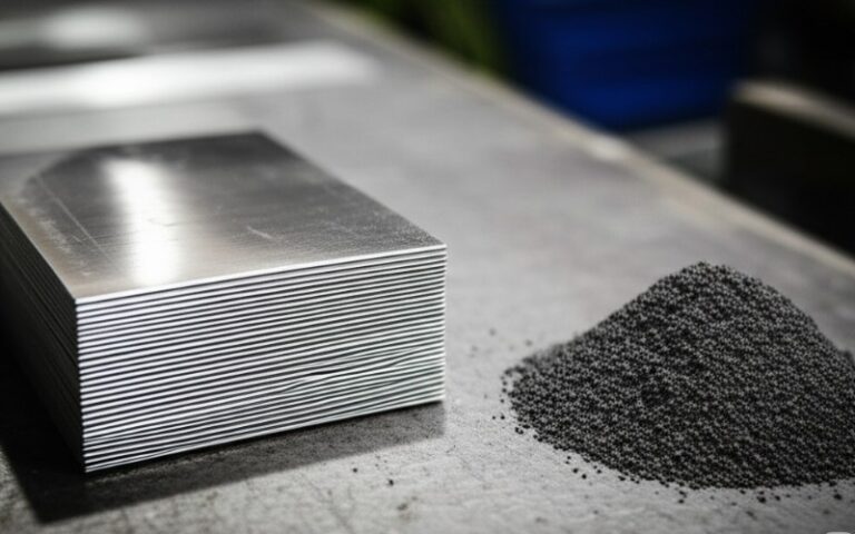
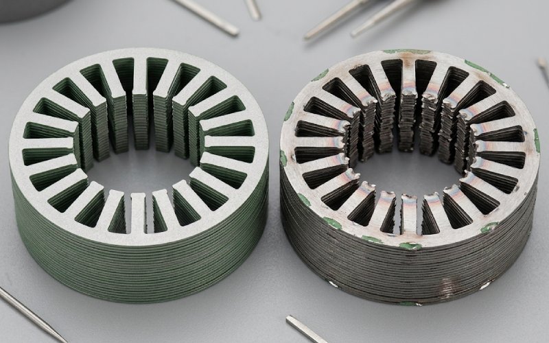
Let Sino's Lamination Stacks Empower Your Project!
To speed up your project, you can label Lamination Stacks with details such as tolerance, material, surface finish, whether or not oxidized insulation is required, quantity, and more.
Motor lamination burr control is not just burr height control.
In lamination stacks, burr-related failure starts when a cut-edge defect becomes an electrical path under real assembly conditions. Burr height matters, yes. So do coating damage, burr direction, stack pressure, joining method, and whether adjacent laminations can form a closed conductive loop. If the loop forms, local circulating current rises. Iron loss rises with it. Heat follows.
So the useful question is not “Is the burr too high?”
It is “Can this stack form interlaminar conductive paths after compression and joining?”
If you need the fast version, use this:
Interlaminar shorts happen when adjacent sheets stop behaving like insulated laminations and start behaving, even locally, like a thicker conductive body.
Usually the chain looks like this:
That sequence matters because many teams inspect only step one.
They measure burr height. Approve the part. Move on.
Then the stack is built, compressed harder, restrained differently, maybe flipped in a way no one tracked, and the real electrical condition changes.
So no, burr control is not a loose-sheet problem. It is a final-stack problem.
Two mechanisms usually overlap.
This is the obvious one. When burrs or damaged edges create metal-to-metal contact between sheets, circulating current can flow across laminations. Once that happens, the stack behaves less like a laminated core and more like a partially shorted section. Local iron loss rises first. Bulk loss may rise later. Sometimes the hotspot shows up before the loss number looks dramatic.
Even without a full interlaminar short, the cut edge is not magnetically neutral. The punching process leaves a strained zone near the edge. Hardening, residual stress, and microstructural disturbance change local magnetic behavior. So a stack can suffer extra loss from edge damage even before a closed conductive loop fully develops.
This is why two parts with similar burr height can behave differently in test.
Same nominal burr. Different edge condition. Different coating survival. Different assembly pressure. Different result.
Burr direction is not a side note. It affects which face mates against which face after stacking. If the active burr repeatedly faces the most vulnerable coated surface, contact risk rises fast under compression.
If lamination orientation is mixed on the line, or if sheets are flipped without control, the electrical result can change even when the measured burr does not.
A burr that looks minor in a loose-sheet inspection can become a real bridge after compression. This is where many quality escapes begin. Resistance at low clamp force tells only part of the story. Production clamp force tells the part that matters.
A small burr on intact insulation is one case. The same burr on crushed or abraded coating is another. In practice, insulation survival near the cut edge often matters more than the burr number printed on the report.
Bonding, welding, interlocking, clinching, clamping. None of these are electrically neutral. Some methods preserve insulation better across the stack. Others introduce local conductive connections, stress concentration, or heat-affected damage. A process that is mechanically stable may still worsen magnetic performance.
Fresh tools can make almost any control plan look good. The real test starts later. Burr growth, edge tearing, and coating damage tend to drift with wear. If you only approve first-article samples, you are not controlling burr risk. You are sampling optimism.
There is no single number that works across all lamination stacks.
The critical threshold depends on sheet thickness, insulation system, burr shape, stack pressure, part geometry, and joining method. A taller isolated burr may cause less trouble than a lower but broader contact area that flattens under compression. This is why average burr height often fails as the main release criterion.
A better control logic looks like this:
That is more work than a single burr limit. It is also closer to what the stack sees.
Punch-die clearance should be treated as a process window, not as a minimum-value game.
Too much clearance tends to increase plastic deformation, fracture severity, and burr formation. Too little clearance can also create edge stress problems. The best result is usually a window that balances clean shearing, manageable burr formation, and limited edge damage for the specific material and thickness in use.
So the wrong question is:
“What is the universal best clearance?”
The better question is:
“What clearance window gives acceptable edge morphology, stable coating survival, and low electrical risk after compression for this steel grade, this thickness, and this tool condition?”
That wording is less convenient. It is the one that works.
When no-load loss drifts up, or when a stack starts showing unexplained hotspot behavior, inspect in this order.
Do not start with theories about motor design unless process evidence points there. First check whether punch condition, regrind interval, edge quality, or burr trend changed.
Confirm how sheets are actually stacked. Not how the process sheet says they should be stacked. Mixed orientation can quietly change contact behavior.
Test under representative stack force. Loose-sheet electrical checks are useful, but they are not enough.
Look for crushed, scraped, or thermally affected insulation near cut edges and joining locations.
A welding parameter shift, restraint pattern change, or interlock adjustment can turn a previously acceptable edge into a short-risk edge.
Bulk loss numbers can hide local trouble. A stack with early hotspot development may be telling the truth sooner than the average loss figure.
That sequence saves time because it follows how burr faults usually enter the stack: edge, insulation, compression, restraint, then heat.
| Control item | What it tells you | What it misses | Better decision use |
|---|---|---|---|
| Average burr height | General edge deterioration trend | Loop formation, coating survival, compression effect | Use as warning signal, not final release logic |
| Burr by side | Which mating surfaces are more dangerous | Orientation mix during stacking | Track punch side and die side separately |
| Tool life count | Wear-related drift across production | Actual electrical consequence | Pair with edge inspection and resistance checks |
| Edge morphology | Shear zone, fracture quality, tearing, burr shape | Final stack electrical behavior | Use to validate clearance window and regrind timing |
| Loose-sheet resistance | Basic insulation condition | Real compressed contact behavior | Never use as the only electrical screen |
| Compressed interlaminar resistance | Actual short risk under load | Local thermal severity over time | Best screening tool before full performance loss shows |
| Joining process audit | Restraint-induced risk and coating damage | Random local faults away from the joint | Review whenever loss trend changes after assembly |
| No-load loss result | System-level symptom | Root cause location | Use as confirmation, not first diagnosis |
| Thermal hotspot screening | Localized fault visibility | Exact geometric source of contact | Useful when loss drift is inconsistent or late |
The inspection plan should match the way the fault develops.
Start at the edge. Then move to the stack. Then move to the assembled core.
Check:
Check:
Check:
A common mistake is skipping the middle stage. Teams inspect cut parts and then jump straight to end-of-line motor data. That leaves the actual failure conversion step unobserved. And that step is usually compression plus joining.
The same lamination edge can behave one way in a bonded stack and another way in a welded or mechanically interlocked stack.
That should not be surprising, but it is often treated as surprising.
Joining does three things at once:
So when burr-related iron loss appears after a joining change, the right conclusion is not always “the burr got worse.” Sometimes the edge stayed similar and the restraint condition changed.
The stack does not care which department owns the cause.
Sometimes it helps. Sometimes it helps less than people hope.
Annealing may recover part of the magnetic damage caused by cutting stress. It can improve edge-related loss that comes from strain and hardening. But it does not magically remove conductive bridges that remain after stacking and joining. If the problem is an actual interlaminar contact path, annealing is not a substitute for fixing the edge condition or the assembly condition that created the bridge.
Use annealing as damage recovery where appropriate. Do not use it as permission to accept unstable burr control.
Use this simple rule:
If burr control is defined only by geometry, the stack is under-controlled.
If burr control is defined by geometry plus electrical behavior under compression, the stack is closer to being controlled.
The main cause is not burr height alone. The real trigger is conductive contact between adjacent laminations after compression or joining. Burrs matter because they help create that contact, especially when the insulation coating near the edge is damaged.
Yes. A small burr can still contribute to extra iron loss if it damages insulation, flattens under pressure, or participates in a closed conductive path. A visibly larger burr is not always the more dangerous one.
Start with tool wear trend, burr by side, lamination orientation, and compressed interlaminar resistance. If those are drifting, the end-of-line loss result is usually a late symptom, not the first useful signal.
It is useful as a trend metric, but weak as a standalone release criterion. It does not tell you whether the final lamination stack will form conductive paths under actual assembly pressure.
Stack pressure can turn marginal edge defects into real electrical bridges. A stack that looks acceptable in loose-sheet inspection may fail once compression forces bring damaged edges into contact.
Yes. Joining method can change pressure distribution, insulation survival, and electrical contact between laminations. That means the same cut edge may behave differently after bonding, welding, interlocking, or clamping.
Yes. Extra no-load loss can come from cut-edge magnetic damage, local insulation breakdown, or restraint-induced contact even when burr height alone does not look extreme. That is why edge morphology and compressed electrical checks matter.
Use it whenever burr trend rises, tool wear drifts, joining conditions change, or no-load loss begins to move without a clear design explanation. It is one of the most useful tests for separating harmless edge variation from real stack-level short risk.
Motor lamination burr control should be defined as short-path prevention in the finished lamination stack, not as simple burr-height control on individual sheets.
That shift changes everything.
It changes what you inspect.
It changes what you trend.
It changes when you stop the line.
It changes which “acceptable” parts are not actually acceptable.
And once that becomes the standard, extra iron loss stops looking random.