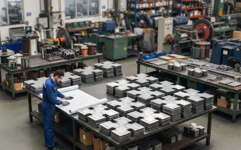
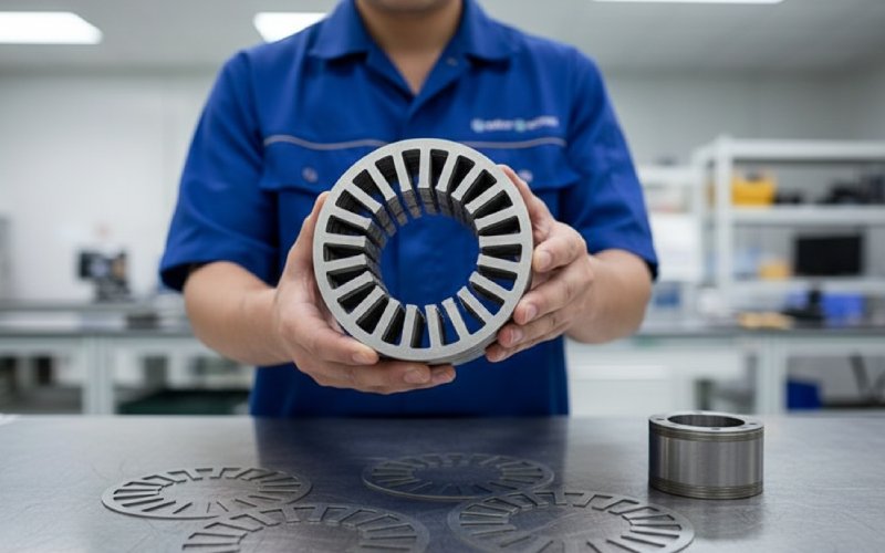
Let Sino's Lamination Stacks Empower Your Project!
To speed up your project, you can label Lamination Stacks with details such as tolerance, material, surface finish, whether or not oxidized insulation is required, quantity, and more.
Forget the datasheet for a moment. Picture your motor first.
Use NOES when:
NOES remains the default core material for most motors and generators because it combines high magnetic saturation, reasonable losses, and low cost, especially when rolled to 0.5–0.2 mm thickness and alloyed with ~0.5–3.5 wt% Si and Al.
Use cobalt-iron when:
Iron-cobalt alloys are at the top in saturation magnetization, around 2.3–2.4 T for typical 35–50 % Co alloys such as Hiperco-type grades, with high Curie temperature.
You are paying almost purely for higher B_sat and thermal headroom.
Use nickel-iron when:
High-nickel Ni-Fe (~79–80 % Ni) gives very high initial and maximum permeability and very low hysteresis losses, but saturation induction is only about 0.8–1.0 T.
Medium-nickel (~40–50 % Ni) alloys sit around 1.5–1.6 T saturation with good permeability – more interesting when you still need some torque density.
Typical values, not a datasheet. Think of them as design “zones”.
| Parameter | NOES (non-oriented electrical steel) | Cobalt-iron (Fe-Co, e.g. Hiperco-type) | Nickel-iron (Ni-Fe, 50–80% Ni) |
|---|---|---|---|
| Typical B_sat (room temp) | ~1.7–2.0 T | ~2.3–2.4 T | ~0.8–1.0 T (80% Ni); ~1.4–1.6 T (40–50% Ni) |
| Relative permeability | Medium to high | High | Very high at low fields (can exceed 10⁵ for 80% Ni) |
| Core loss | Baseline; improved with thin gauge & higher Si/Al | Comparable or better at same flux for some grades, but strongly processing-dependent | Very low hysteresis at low flux; loss rises quickly as you approach saturation |
| Typical lamination thickness | 0.50–0.20 mm for mainstream; high-speed EV trends toward ≤0.20 mm | Usually thin strip (0.20–0.10 mm) | Often 0.35–0.10 mm strip or tape-wound cores, depending on alloy and supplier |
| Mechanical behavior | Good ductility; robust in stamping | Strong but more notch-sensitive; stress and heat treatment critical | High-Ni versions can be quite soft and mechanically weaker; processing damage is easy |
| Raw material cost (very rough) | Low | High | Medium to high (80% Ni is expensive) |
| Typical lamination stack roles | General-purpose rotors & stators, EV traction motors, industrial drives, generators | High-speed rotors, aerospace generators, compact high-power stators, magnetic bearings | Resolvers, sensors, instrument transformers, specialty stator segments, magnetic shielding |
Use this table as a sanity check. If your use-case doesn’t sit anywhere near the “typical roles” row, rethink the material choice.
Most teams jump straight into “Is cobalt-iron worth it?”. A better order:
Once this is pinned down, the NOES / Co-Fe / Ni-Fe decision is usually much less “mystical”.
You already know the basics: Fe-Si alloy, ~0.5–3.5 % Si (plus Al), isotropic in-plane properties, rolled and coated for rotating machinery.
What matters in practice:
High-speed automotive motors have already moved from 0.35 mm toward 0.27–0.30 mm and thinner gauges for lower iron loss; this trend is well documented in traction motor materials articles.
If your electrical frequency is below ~400 Hz and efficiency targets aren’t extreme, a good grade of 0.35 mm NOES often meets the spec with far less pain.
So if your electromagnetic model demands >1.8 T in teeth at peak torque, you’re in cobalt-iron territory or re-geometry territory.
Typical cases where NOES lamination stacks are still the rational choice:
In short: if you can meet torque, efficiency, and temperature with NOES, moving to a more exotic alloy needs a hard financial justification.
Iron-cobalt alloys are the heavy artillery. High B_sat (often ~2.35–2.4 T), high Curie temperature, decent permeability.
So, flux density and temperature margin. That’s what you’re paying for.
The obvious cost: cobalt is expensive and volatile. The less obvious costs:
Situations where Fe-Co laminations are usually justified:
Common design pattern:
Use cobalt-iron where flux density is highest (e.g. rotor, tooth tips) and NOES elsewhere, if your lamination stack supplier can manage hybrid stacks and compatible annealing routes.
If you’re considering Fe-Co solely because “others in the segment are using it”, double-check the flux map. The gain might be marketing, not electromagnetics.
Nickel-iron alloys are broad family. They aren’t all the same, and that matters.
Both groups are available as strip, sheet, and tape-wound core feedstock, and both see more use in transformers, sensors, shielding, and instrumentation than in main traction rotors.
With Ni-Fe, the process can make or break the part:
Common, sensible use-cases:
If your 200 kW traction motor concept is “entirely nickel-iron lamination stacks”, something is off.
Material choice without process thinking is half a decision.
Key process-material interactions for B2B lamination stack projects:
For NOES, stamping + a reasonable anneal is usually sufficient. For Co-Fe and high-Ni, discuss with your lamination supplier how they restore properties after cutting.
Each method adds its own “penalty”:
When you send a lamination stack RFQ, include the material + thickness + assembly method as a coupled decision, not separate checkboxes. That’s where many “we picked Fe-Co but saw no gain” stories come from.
Some quick sketches – not full designs, but enough to anchor material choice.
Likely outcome:
Here, cobalt-iron starts to look like the “standard” option:
Typical outcome:
When you send an RFQ to a B2B lamination stacks manufacturer, the fastest way to a sensible quote is to phrase your needs in terms that connect directly to material selection:
A good lamination specialist will then propose specific grades (e.g. named NOES grade, a particular Fe-Co alloy, or a Ni-Fe composition) and thicknesses that match these constraints.
Yes, for many platforms. Thin-gauge NOES with optimized silicon/aluminum content and coatings is still the most widely used core material for motors and generators, including EV traction, because of its balance of cost, availability, and magnetic performance.
Some high-end or niche EV programs adopt cobalt-iron in specific components (often the rotor) when they need extra torque density and are willing to accept cost and processing complexity.
A pragmatic approach:
Fix your lamination material to NOES and try a thinner gauge (e.g. 0.35 mm → 0.25 mm → 0.20 mm) while watching core loss and manufacturing impact.
If you still cannot hit torque density or efficiency targets without pushing flux density to uncomfortable levels (>~1.8 T in key regions), then model a cobalt-iron option.
Compare cost per kW and per machine, including extra processing steps and scrap risk.
If thinner NOES plus geometry tweaks can reach the target, cobalt-iron is rarely justified.
Technically yes, but it’s unusual.
Medium-Ni alloys (around 50 % Ni) have decent saturation and permeability and can be made into laminations, but their cost and processing sensitivity usually make NOES or Fe-Co better options for high-speed rotors unless you have a very special requirement (for example, a combined measurement/motor function).
High-Ni (~80 %) alloys saturate too low for practical high-power rotors.
Ordering Fe-Co because “we need a high-performance motor” without:
Setting a clear flux density target
Planning the post-punching anneal
Checking stack assembly stresses
The result: expensive laminations with only marginal performance gain over a well-chosen NOES grade.
It can.
For very high-speed rotors, bonded stacks often suit Fe-Co better than heavy welding because they reduce local heat-affected zones and distribute stress more evenly.
NOES is more forgiving and works well with interlocking, welding, or bonding.
Ni-Fe (especially high-Ni) is more sensitive to local heating, so welding must be tightly controlled; bonding or clamping is often preferred.
Always discuss the assembly method with your lamination supplier at the same time as the material choice.
Earlier than most teams do it.
If you involve them once you’ve already frozen the material, thickness, and stack length, you turn them into a vendor. If you involve them when you still have a window on material family, thickness, and assembly method, you gain process insights that often save cost and time.
Summary
Pick the lamination material by starting from your flux density, frequency, thermal, and cost targets. In many cases, optimized NOES lamination stacks are still the rational default. Cobalt-iron and nickel-iron step in only when a specific, quantifiable requirement pushes you outside NOES’ comfort zone.
Once that is clear, the rest is just implementation detail: thickness, coatings, and how you turn strip into a rotor or stator stack that behaves the way your FEA promised.