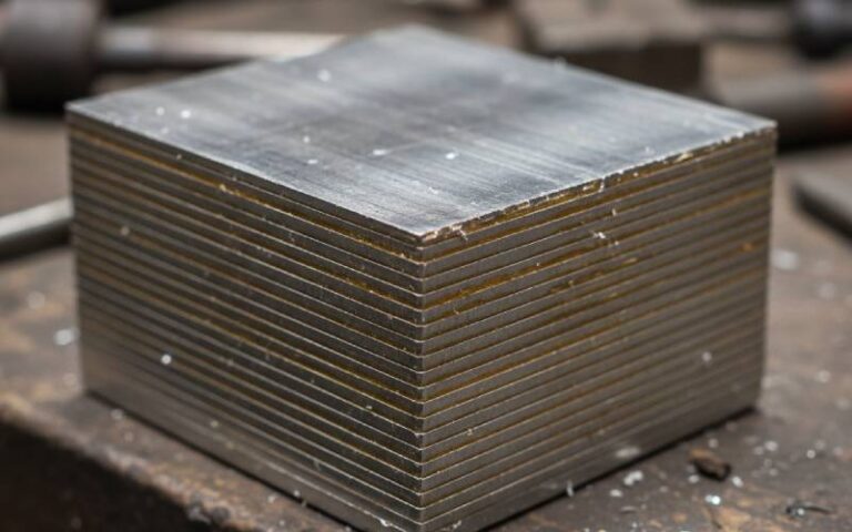
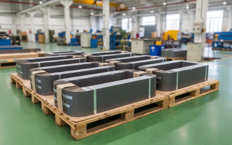
Let Sino's Lamination Stacks Empower Your Project!
To speed up your project, you can label Lamination Stacks with details such as tolerance, material, surface finish, whether or not oxidized insulation is required, quantity, and more.
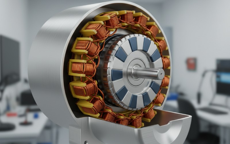
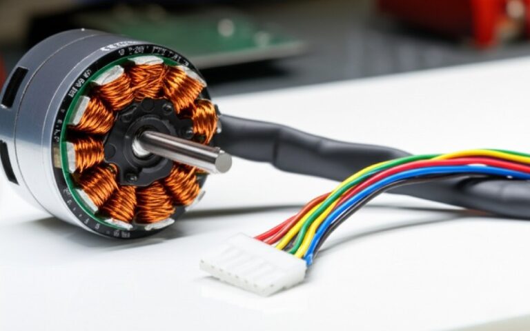
When engineers argue about motors, they usually talk about magnets, copper fill, or inverter tricks. But quietly, underneath all of that, one very simple decision is steering almost everything:
How many stator slots, and how many rotor poles, are you using?
That slot/pole combination decides whether your motor hums smoothly or screams, whether your magnets run cool or cook, and whether your machine is easy to manufacture or a nightmare. Recent research keeps coming back to the same conclusion: slot/pole choice is the first design decision you should get right, especially with modern fractional-slot concentrated winding (FSCW) machines.
Let’s fix terminology for a 3-phase machine (most of what follows generalises easily):
q) – the key ratio:[ q = \frac{Q}{m \cdot 2p} \quad \text{(with } m = 3 \text{ for a 3-phase machine)} ]
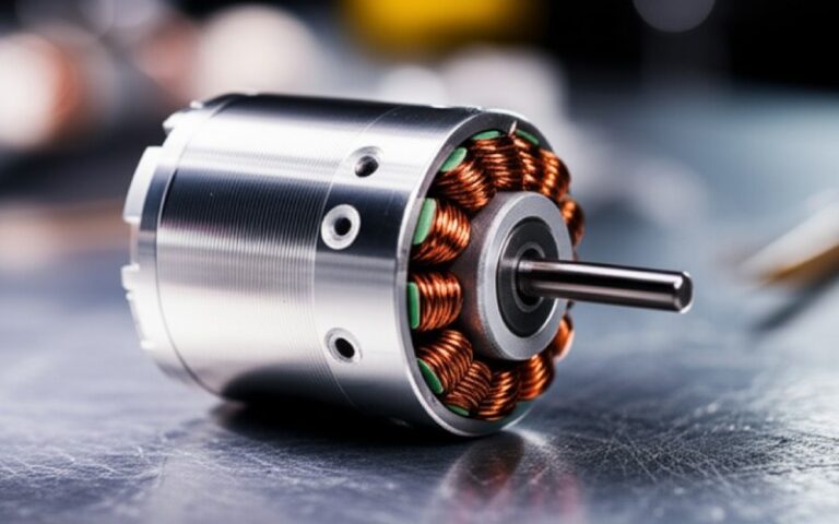
This single number, q, tells you whether your winding is “integral-slot” (integer q) or “fractional-slot” (non-integer q). Fractional-slot concentrated winding (FSCW) machines – now common in EVs, aerospace, and generators – deliberately choose q < 1 for high torque density and short end turns.
Historically, big industrial motors started with integral-slot distributed windings:
q = 36 / (3·4) = 3Then high-pole-count PM machines and direct-drive applications arrived. To keep copper short and simplify winding, designers moved to fractional-slot concentrated windings (FSCW) where each tooth carries a concentrated coil and q is fractional.
This wasn’t just a winding fashion change – it fundamentally changed how we pick slot/pole pairs. Instead of “whatever gives a nice distributed winding”, you now target:
q:q ≥ 2 → “classical” distributed winding (e.g., 36/4): smooth torque, but more copper length and more complex winding.1 ≤ q < 2 → compact distributed or semi-concentrated; often used in industrial PMSMs.0.25 ≤ q < 1 → fractional-slot concentrated; dominates modern high-pole PM machines and wheel-hub motors.q < 0.25 → extreme fractional; usually too many poles for the slot count, bringing strong parasitics unless very carefully designed.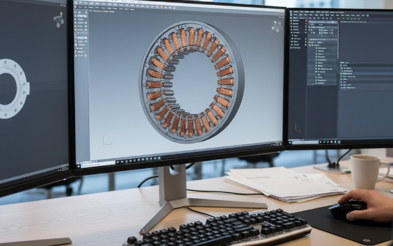
Once you pick Q and 2p, your stator geometry space collapses down to a smaller set of viable options:
q inside a comfortable range (≈0.25–3) for my manufacturing and winding type?”Change the slot/pole combination and you change the rotor’s entire job: how it carries flux, how magnets are sized and placed, and which harmonics hit the magnets and shaft.
For surface-mounted PMSMs and SPM machines, recent comparative studies show that pole/slot choices strongly affect:
For interior PM (IPM) or reluctance machines, the same slot/pole pair dictates where you can put flux barriers and how well your d- and q-axis inductances separate – crucial for field-weakening.
Below is a practical snapshot of 10 common or illustrative slot/pole combinations for 3-phase motors. These aren’t “good vs bad” labels – they’re starting points to think about how stator and rotor choices are linked.
qis calculated for 3-phase (m = 3):q = Q / (3·2p)
| # | Slots / Poles (Q / 2p) | q (slots / pole / phase) | Winding type (typical) | Typical application flavour | Stator implications | Rotor implications |
|---|---|---|---|---|---|---|
| 1 | 36 / 4 | 3.0 | Integral, distributed | Classic industrial induction/PMSM | Many small slots, sinusoidal MMF, low torque ripple, excellent efficiency; more complex winding & longer end turns | Few poles → high base speed; low cogging; magnets (if PM) can be wide and robust |
| 2 | 12 / 4 | 1.0 | Integral / semi-distributed | Compact general-purpose PMSM | Simpler lamination, reasonable MMF quality; good compromise where you want fewer slots | 4-pole rotor, simple magnetisation; good for moderate speed & cost-sensitive designs |
| 3 | 9 / 8 | 0.375 | Fractional, concentrated | Small BLDCs, fans, hobby drones; heavily studied 8p9s family | Very few slots → wide teeth; easy to wind tooth coils, but higher risk of saturation and fewer degrees of freedom to shape harmonics | High pole count for such low slot count; can achieve high torque density, but torque ripple and acoustic noise can be significant if not mitigated |
| 4 | 12 / 8 | 0.5 | Fractional, concentrated | Servo motors, pumps, compact drives | More slots than 9/8 → narrower teeth, better harmonic control; coil insertion still easy | 8-pole rotor offers higher torque at lower speed vs 4-pole; cogging manageable with slot/pole choice and modest skew |
| 5 | 12 / 10 | 0.4 | Fractional, concentrated | High-performance PMSMs, direct-drive, some EV auxiliaries; 12s/10p is a “modern workhorse” | High flexibility in tooth shaping and slot opening; good compromise between slot count and manufacturability | 10 poles → strong torque at low speed; high cogging frequency, allowing low cogging amplitude with proper pole arc and notching |
| 6 | 18 / 16 | 0.375 | Fractional, concentrated | Higher-torque SPM/IPM for robotics or traction | More teeth for better flux distribution and thermal path than 12-slot families; coil pattern still manageable | 16 poles give high torque density; rotor needs careful magnet segmentation and pole-arc design to control losses and ripple |
| 7 | 24 / 22 | ≈0.364 | Fractional, concentrated | Aerospace & compact high-torque machines | Densely toothed stator; allows refined slot opening tweaks and possibly tooth notches to tune cogging | 22-pole rotor at modest diameter → very high torque at low speed; must carefully analyse mechanical stresses and magnet losses |
| 8 | 27 / 22 | ≈0.409 | Fractional, concentrated | Traction or generator designs where lamination reuse drives odd slot counts | Slightly “asymmetric” feel compared to 24/22; gives unusual phase belt patterns that can help with specific harmonic targets | Similar torque benefits to 24/22, but more complex optimisation of magnet layout and pole arc, often chosen when you inherit a 27-slot stator |
| 9 | 36 / 30 | 0.4 | Fractional, concentrated | Large PM direct-drive (wind, wheel-hub, big robotics) | Lots of slots → good control of radial forces and thermal path; coil ends still relatively short if tooth coils are used | 30-pole rotor gives very high torque at low RPM; mechanical integrity and magnet retention become critical design drivers |
| 10 | 48 / 40 | 0.4 | Fractional, concentrated | Large low-speed generators and direct-drive systems | Even more granular tooth structure; great for waveform shaping but more expensive laminations | 40 poles → extreme torque at low speeds; finite-element analysis is essential to manage losses, saturation, and vibration |
The big picture: as you slide from (36/4) down towards (48/40), you trade speed for torque, and “pretty sinewaves” for compact high-pole-count machines that demand careful harmonic and mechanical control.
A lot of academic work has tried to answer “what’s the best slot/pole pair?” for different machine types. The honest summary is: it depends on your priorities – but there are patterns.
Key findings from recent literature on PM machines with concentrated windings:
Qs = 9 + 6k with p = Qs ± 1 (which includes 9/8) can have very high torque ripple and unbalanced magnetic forces unless carefully mitigated.q > 0.25.q between ~0.3 and 0.7 if you want compact FSCW designs.Here’s a human-friendly way to pick a slot/pole combination for a new motor, that reflects what high-end research and real design offices actually do.
q and quickly reject anything outside your manufacturing comfort zone.If we think of “Motor Core 10” as the tenth essential design decision, slot/pole combinations probably belong in the top three. Everything else – magnet grade, inverter sophistication, cooling – is built on this foundation.
So next time a datasheet casually says “12-slot, 10-pole”, don’t just nod and move on. Pause and ask:
Once you start seeing slot/pole combinations as design levers instead of just numbers, you’ll find it much easier to out-engineer competitors – and to have better, more grounded conversations with your lamination suppliers and motor manufacturers.